Help! Controller problem

kokosu

Finding my (electric) wheels
Nov 26, 2020
13
0
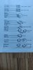
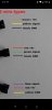
Hello! I have this controller with lcd :
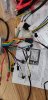
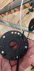
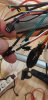
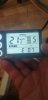
with 250w rear drive motor. Well I do not know where to start, because the motor works only when I do not pedalling also it's enough to start the motor only to touch the pas sensor of one of the magnets. I can also change the way it's spins(slower of faster) from lcd. I have checked the pas wiring, there are only 3 wires, seems ok . I do not know what to do. The error on the lcd is 07. Means motor problem...
please help
 

vfr400

Esteemed Pedelecer
Jun 12, 2011
9,822
3,985
Basildon
I think you have the PAS connected to the wrong connector. It's connected to the throttle one instead of the PAS.

When you connect it to the right connector, make sure that the sequence of the wires is correct - normally red to red, black to black and whatever colour the third wire is to the thirs one on the other side. If you're not sure about the sequence, tell us which colours you have on each side.

If you can't figure out the connectors, show us clear actual photos of what you have.
 
Last edited:

kokosu

Finding my (electric) wheels
Nov 26, 2020
13
0
Here is the wiring. Actually I do not know what boost is. Maybe there is a mistake in the manual41055
 

vfr400

Esteemed Pedelecer
Jun 12, 2011
9,822
3,985
Basildon
OK, this is my last guess, which is all I can do without photos, and you didn't say whether you checked that you're connected to the right connector It's really frustrating when people don't help us to help them.

You have the self-study connectors connected. They should be disconnected for normal use.

Boost is the connector that you need to connect the pedal sensor to! Speed control is for a throttle.
 

kokosu

Finding my (electric) wheels
Nov 26, 2020
13
0
I'm sorry, you are right! I'll give you as many pictures you want. Please tell me what picture do you want! 41060
 

kokosu

Finding my (electric) wheels
Nov 26, 2020
13
0
I tried to mount the pas sensor to the boost terminals. Nothing happened. I only have to touch the pas sensor to one magnet and the motor starts. And it stops when I start pedalling
 

Nealh

Esteemed Pedelecer
Aug 7, 2014
19,991
8,173
60
West Sx RH
I tried to mount the pas sensor to the boost terminals. Nothing happened. I only have to touch the pas sensor to one magnet and the motor starts. And it stops when I start pedalling
Show us a pic of the boost & PAS connections as one connected up.
How many magnets does the PAS disc have ?

I was going to mention earlier what boost and spd control referred to, but as vfr was already on the case one doesn't like to step on others toes unnecessarily.
 

kokosu

Finding my (electric) wheels
Nov 26, 2020
13
0
Here is the pas sensor. It has yellow(-) red(+) and blue(signal). There are 5 magnets. The boost I did not intend to use it and I do not have a device for acceleration.
41067
 

kokosu

Finding my (electric) wheels
Nov 26, 2020
13
0
The black socket with black red and blue is the boost connection
41068
 

vfr400

Esteemed Pedelecer
Jun 12, 2011
9,822
3,985
Basildon
You can't connect to the throttle connector, like you have. Every time a magnet passes the sensor, you'll get full throttle signal. The red, blue and black connector is the correct one.

Your hall sensor connector also has the wrong sequence. The red must go to red and the black to the black. Your Yellow and red are crossed over. I can't see the others.
 

Nealh

Esteemed Pedelecer
Aug 7, 2014
19,991
8,173
60
West Sx RH
The Boost wire is the controller PAS connection as it has 5v, if it isn't connected how do you expect PAS to work ?
Vfr has beaten me to it.

The throttle connects to the spd control switch as indicated by the 4.3v.
The White wire is commonly an indicator that it is the signal/speed wire this is nearly always either the throttle or an ext spd sensor sign.
 
Last edited:

Nealh

Esteemed Pedelecer
Aug 7, 2014
19,991
8,173
60
West Sx RH
All I can see is a Red I assume to Yellow & Blue to White no Black anywhere, Red/ v+ to Yellow/Gnd ? makes no sense. The pics are far from clear what is connected to what.

Hall sensor as mentioned isn't correct they should all go colour to colour.
 
Last edited:

kokosu

Finding my (electric) wheels
Nov 26, 2020
13
0
The pas sensor from the bike has yellow(which is ground) red for+ and blue for signal. I found this on internet. Yes because I can change speed of the controller from lcd choosing level for assistance I'm assuming too that white , red and black is for throttle. Already tried to switch to boost jack to see what's there. But the motor is not spinning. So maybe this controller has no assistance for pas? I made the pictures working on the bike and changing wires all the time, not founding a solution. Do you want to make another picture clearer for something else?
 

vfr400

Esteemed Pedelecer
Jun 12, 2011
9,822
3,985
Basildon
The pas sensor from the bike has yellow(which is ground) red for+ and blue for signal. I found this on internet. Yes because I can change speed of the controller from lcd choosing level for assistance I'm assuming too that white , red and black is for throttle. Already tried to switch to boost jack to see what's there. But the motor is not spinning. So maybe this controller has no assistance for pas? I made the pictures working on the bike and changing wires all the time, not founding a solution. Do you want to make another picture clearer for something else?
I told you in post #2 that you have your PAS connected to the wrong connector. You havent confirmed that you have fixed it.
I told you in post #10 that you have the wrong connection sequence in your hall sensor connector. You still haven't confirmed that you have fixed it.
How can anyone help you if you ignore the advice you're given?

When you have the correct connections and correct sequence of wires in them, you must do the self-study procedure, which is explained in the instruction sheet that you got with the controller.
 

kokosu

Finding my (electric) wheels
Nov 26, 2020
13
0
Thank you for all support! Due to the problems I have I did not made any permanent wires connections. There are some wires that are not the same color with the schematic. I made it that way to change wires between more rapid and simple. I do not took all the wires and try them in a random way. I also have a simple multimeter and before making a change I'll double check I have to admit that I did not made that self learning procedure( I did not find anything written about that in that paper that came with controller. The only thing is written the self study wire. Already tried that and changes the sense of rotation of motor). But with the pas sensor in the boost jack nothing happened.i'm thinking to try and double check the controller menu once again. But with the wires from pas sensor in boot jack the motor is not spinning. The pas sensor that I have seems to be the last in the picture

41080
 

kokosu

Finding my (electric) wheels
Nov 26, 2020
13
0
Thanks for all the support! . Yes I used the pas sensor in the boost jack and it's working. I have a lot of wires lying around on the bike, but now I can start and get everything nicer. It seems the bike is working with electric motor assistance. I do not know yet if I'll use the throttle function. As I understand there are some resistors and depending on the tension in the white wire will activate the acceleration. Still have the error 07 on the display. Will see after first ride... All the best to everyone!41087
 

Nealh

Esteemed Pedelecer
Aug 7, 2014
19,991
8,173
60
West Sx RH
It is quite simple to wire up, if one reads carefully that which others are saying.
 

Nealh

Esteemed Pedelecer
Aug 7, 2014
19,991
8,173
60
West Sx RH
The error code is hall sensor, this you have been told already. More then one hall sensor is connected to each other incorrectly, the 6 thin motor wires that go in to the White block should be colour to colour. Red and Yellow are incorrect and the others we can't see properly.
 

kokosu

Finding my (electric) wheels
Nov 26, 2020
13
0
Well the white jack from controller was not the same as the motor was. The one with 6 wires. So I had lying around one that was exactly matching that one and it was the negative, perfect match. But it came with wires already, not the same color order like controller. I matched the motor color wires with the controller color wires. That explains the picture.