E10 error on my new ebike

Albion

Finding my (electric) wheels
Jun 29, 2021
22
4
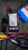
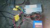
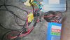
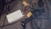
Hi, I have a 48v 1000w front wheel conversion which I have had no problem with. So I decided to buy my sister one as a present. It wasn't the same model but still 48v 1000w. I hooked it up and it went ok but spun backwards. For some reason when I turned the wheel the other way around it would not match up with the forks so I looked online to find a way to reverese the polarity. Someone posted to change any of the 3 phase wires, so I tried it. First I tried switching green and blue and got a rocking motion from the motor. So then I switched green and yellow but nothing happened and nothing has happened since. The unit has gone completely dead. I have power to the throttle as it illuminates and the LCD comes on but shows error code E10. I wondered if anyone has any suggestions. Thanks for any help.

Best regards,

Albion
 

Andy-Mat

Esteemed Pedelecer
Oct 26, 2018
2,214
561
77
I assume that for some reason a hall effect sensor has got damaged, which must be "swapped" with the motor leads when they got swapped. Is my best guess.
These motors have some similarities with 3 phase motors, but the hall effect sensors are needed to switch power to the 3 fields of most e-bike motors today....
May i suggest a tester, which costs little, after you have returned the wiring back to its original state.
Here are some YouTube videos to help you:-
Remember, not all testers will have connectors for every single component on any e-bike that fit. So you may need to adapt using say Croc Clips, to get the electrical connection needed.
Best of luck.
regards
Andy
 

Albion

Finding my (electric) wheels
Jun 29, 2021
22
4
I assume that for some reason a hall effect sensor has got damaged, which must be "swapped" with the motor leads when they got swapped. Is my best guess.
These motors have some similarities with 3 phase motors, but the hall effect sensors are needed to switch power to the 3 fields of most e-bike motors today....
May i suggest a tester, which costs little, after you have returned the wiring back to its original state.
Here are some YouTube videos to help you:-
Remember, not all testers will have connectors for every single component on any e-bike that fit. So you may need to adapt using say Croc Clips, to get the electrical connection needed.
Best of luck.
regards
Andy
Hi, thanks for the info. I've ordered one already. I'll give it a go. If it tells me a hall sensor isn't working, what could I do? All the wires look fine so I'm guessing it would be the hall sensor itself. Are these inside the controller? I'm guessing if I locate the faulty one, the first thing to do is test the continuety from the wire at the controller end to the socket. This will tell me if it's the wire or not. If the wire is ok then I would have to replace the sensor itself. Is this correct?
 

vfr400

Esteemed Pedelecer
Jun 12, 2011
9,822
3,985
Basildon
It sounds like either you had some bad advice or you didn't understand it or you you didn't recognise that advice only applies to some circumstances and can have bad consequeces in others.

For some sensored motors and their associated controllers, you can change their direction, but not by any of the ways you tried. You can swap ant two phase wires plus the correct two hall wires. If you use any other method, the motor won't be able to turn, and if you attempt to give full power, you will blow the controller sooner or later - normally seconds rather than minutes.

Some controllers have self-recognition wires such that when they're joined, the controller does a self diagnosis of the hall and phase wire connections and figures out which sequence to fire the motor pulses. Each time it does the diagnosis, it reverses the direction of the motor. once the motor rotates the correct way, you must disconnect those wires, otherwise it'll start running backwards again.

You need to show us which controller you have. I don't mean the label on it,instead we need to see the wires and connectors. A link to the kit would also help. That's also, not or.
 

vfr400

Esteemed Pedelecer
Jun 12, 2011
9,822
3,985
Basildon
Hi, thanks for the info. I've ordered one already. I'll give it a go. If it tells me a hall sensor isn't working, what could I do? All the wires look fine so I'm guessing it would be the hall sensor itself. Are these inside the controller? I'm guessing if I locate the faulty one, the first thing to do is test the continuety from the wire at the controller end to the socket. This will tell me if it's the wire or not. If the wire is ok then I would have to replace the sensor itself. Is this correct?
You just wasted your money. All you need is a normal multimeter, which will be much more useful and versatile than that thing. I have three of those testers, and I think I used one once in more than 10 years of working on ebikes.
 

Albion

Finding my (electric) wheels
Jun 29, 2021
22
4
It sounds like either you had some bad advice or you didn't understand it or you you didn't recognise that advice only applies to some circumstances and can have bad consequeces in others.

For some sensored motors and their associated controllers, you can change their direction, but not by any of the ways you tried. You can swap ant two phase wires plus the correct two hall wires. If you use any other method, the motor won't be able to turn, and if you attempt to give full power, you will blow the controller sooner or later - normally seconds rather than minutes.

Some controllers have self-recognition wires such that when they're joined, the controller does a self diagnosis of the hall and phase wire connections and figures out which sequence to fire the motor pulses. Each time it does the diagnosis, it reverses the direction of the motor. once the motor rotates the correct way, you must disconnect those wires, otherwise it'll start running backwards again.

You need to show us which controller you have. I don't mean the label on it,instead we need to see the wires and connectors. A link to the kit would also help. That's also, not or.
Not to worry, it only cost me 11.56 so I'm not too fussed. I have a multimeter too so can use that at any point. I have a soldering iron on stand by if I need to whip out a component.
 
  • Like
Reactions: Andy-Mat

vfr400

Esteemed Pedelecer
Jun 12, 2011
9,822
3,985
Basildon
You don't provide a link to the listing.

I see that your ignition wire (thin red) is not connected. I'm guessing that's intentional. If you put a switch on that wire, you can switch the whole electrical system on and off with it. Any reliable low power switch will do. You won't need a switch on the battery then.

E10 is communicating error between the LCd and the controller, for which there can be a number of reasons. I think you should go back to basics and do all the normal tests and measurements which should reveal the cause of your problem. Set all the wiring back to how it was when you received the kit, then do the tests:

1. Measure the voltage at controller's battery connector. Obviously should be battery voltage. 36v - 42v for a 36v battery would be an acceptable range.
2. Measure the voltage on the 5v rail. You can measure that between any ground (black) and any of the reds going to throttle, PAS or motor halls. It should be around 5v.
3. Check throttle signal wire, which is the one that's not red or black. Should give about 1v to 4v when you twist the throttle. If there's more than one wire, your meter will find it. It's the one that's between 1v and 4v, assuming that it works.
4. Check that the PAS is pulsing. Measure the PAS signal wire while turning the pedals slowly. Should pulse 5v on and off every time a magnet passes the sensor. the signal wire is the one that's not red or black.
5. Check the motor hall signal wires (blue green and yellow) on the connector at the controller. They should each pulse with 5v going on and off as you rotate the wheel BACKWARDS.

6. Mosfet test. Disconnect the motor cable and battery from the controller. measure the resistance (200k scale) between the red battery connection and each of the three phase wire connections, then repeat with the black battert wire. eack set of 3 readings should be the same as each other and in the range 7K -22K. Though can be higher as long as they're all the same. Due to the capacitor across the battery wire, you can get a constantantly changing measurement while it charges. In that case, try swapping your probes round. Even though can be a moving result, the only important thing is that all three move in a similar way.

If your bike passes all those tests, it should work, so then you can look at any settings or other logical causes, like stuck brake switches, PAS installed backwards.

When checking whether the motor will work, always disconnect all unessential connectors, like PAS (if you have a throttle). lights and brakes.
 
  • Like
Reactions: Tony1951

Albion

Finding my (electric) wheels
Jun 29, 2021
22
4
Hi, thanks vfr400. I decided to wait for my tester to arrive. It should be here tomorrow or Thursday. It will be easier to hook up and easier to read. I'll let you know the results. By the way, can you tell me exactly how to hook up the red wire. Does it go between the controller and the throttle?

Best Regards
 

Nealh

Esteemed Pedelecer
Aug 7, 2014
19,994
8,173
60
West Sx RH
The testers only gives you a LED indication that something may be working but no real world reading of any figures, the meter readings are simpler to understand with phases you are looking for a specific range in numbers when ohms testing and like wise with any 5v reading you want to see any 5v switching on/off correctly.
It's like battery testing you could have an LED to say yes power is seen but it doesn't really give any useful info to help, the tester is much the same and doesn't help you to understand much except that a little LED blinks or not.
 

Albion

Finding my (electric) wheels
Jun 29, 2021
22
4
Ah, sounds like I'll have to have a go then. I think it will be the weekend though cos I'm a little buy at the moment. The Ebay shop wants me to take it to a repairer and send the bill to them but I wanted to have a go first. It would save all the faff if I could just isolate the problem at least. Does anyone know of a E-bike repair shop? I live in Sheffield.
 
  • Like
Reactions: Andy-Mat

Nealh

Esteemed Pedelecer
Aug 7, 2014
19,994
8,173
60
West Sx RH
Tbh no LBS will really touch it because they haven't a clue of how to test, unless it is a branded mid drive type bike which plugs in to a pc. The they are the cleverest ebike repairers in the country, I believe the actual knowledge base amongst most LBS selling ebikes is pretty non existent when it comes to hands on testing of basic dc electrics.
Only some one like Woosh would be tempted or a competent diyer, that's why we end up helping so many people.
 

Nealh

Esteemed Pedelecer
Aug 7, 2014
19,994
8,173
60
West Sx RH
Though with meter testing it may mean you can't facilitate a physical repair sometimes, it does/can pin point where the failure is and a possible reason why, in turn reducing the need to guess at what is wrong. In the past we have had folks willy nilly replacing parts and still none the wiser as the bikes still don't work.
 

vfr400

Esteemed Pedelecer
Jun 12, 2011
9,822
3,985
Basildon
Hi, thanks vfr400. I decided to wait for my tester to arrive. It should be here tomorrow or Thursday. It will be easier to hook up and easier to read. I'll let you know the results. By the way, can you tell me exactly how to hook up the red wire. Does it go between the controller and the throttle?

Best Regards
The thin red wire is the ignition wire. It should be connected anywhere where it gets the battery voltage, like the main battery connector red. I wasn't thinking before. You don't need a switch because you have one with the LCD. The red wire runs up to the LCD to power it, when on, the LCD connects the red to the blue, which runs back to the controller to power it
 

Albion

Finding my (electric) wheels
Jun 29, 2021
22
4
I've just blown my tester up. I put the alligator clips onto the throttle connector but they are so close together they must have touched. I can't see how you are supposed to do this. I would need a male connector to loose wires on the throttle. Anyway, I can't see an internal fuse so I guess it's toast.
 

vfr400

Esteemed Pedelecer
Jun 12, 2011
9,822
3,985
Basildon
The guy that keeps recommending those testers has never actually used one. I told you that it was a waste of money. You have to make cable adapters for most bikes to use the tester. By the time you've done that, you would have had your bike tested and fixed using a normal meter. Those meters were quite useful about 10 years ago, when Chinese bikes had a fairly standard wiring layout, and you had about a 50% chance of being able to connect directly, but they're pretty well useless today.
 

Albion

Finding my (electric) wheels
Jun 29, 2021
22
4
I've just found another way to proceed. I've seen a throttle and controller on ebay for 31 pounds 19 pence. It's 48v 1000w so it would run it and the sockets can be wrong because I can swap them over from mine if I need to. That would't break the bank and it would be an easy fix. Do you think I could trust that the motor in the wheel is ok before I buy?
 

Albion

Finding my (electric) wheels
Jun 29, 2021
22
4
The guy that keeps recommending those testers has never actually used one. I told you that it was a waste of money. You have to make cable adapters for most bikes to use the tester. By the time you've done that, you would have had your bike tested and fixed using a normal meter. Those meters were quite useful about 10 years ago, when Chinese bikes had a fairly standard wiring layout, and you had about a 50% chance of being able to connect directly, but they're pretty well useless today.
Yes, I wish I would have heard your opinion before I bought. I can't believe there wasn't an internal fuse of some kind.
 

Nealh

Esteemed Pedelecer
Aug 7, 2014
19,994
8,173
60
West Sx RH
Hasn't used one but must have shares in them the way he keeps recommending them. Not forgetting this is a bloke who recommends puts rotors on backwards.
 

Albion

Finding my (electric) wheels
Jun 29, 2021
22
4
The thin red wire is the ignition wire. It should be connected anywhere where it gets the battery voltage, like the main battery connector red. I wasn't thinking before. You don't need a switch because you have one with the LCD. The red wire runs up to the LCD to power it, when on, the LCD connects the red to the blue, which runs back to the controller to power it
Hi, I've just successfully tested the controller and it seems ok. I got the reading from .85 to 3.6 volts so I'm assuming that's a decent range. I tested the 5v rail and got around 4.8v. The main power source came to 53v which is conclusive. But the mosfet test proved negative. Yellow and green came to 15k with the red wire and 8k with the black wire which was ok. But the blue phase tested zero with red and slowly climbed to 8k with black (a very slow climb). The next test will require me to rotate the wheel so I will do that later when I can go outside.

f the next tests show the wheel to be working. then I can go ahead and buy another controller. I don't think I want to mess about swapping components.

Thanks for your help so far. It has all been worthwhile now I can see a clearer picture.
 
Last edited: