Ebike dropped from 3 speed to 2 speed..?

Planemo

Pedelecer
Jun 30, 2015
201
80
Well to add to my recent bike theft woes Mrs P has just told me that her bike was 'playing up' over the last week, particularly around speed settings. This is on a fairly old cheap Chinese kit 36v using a Bafang front motor, rear rack battery/controller combo and 3 speed '790' handlebar controller. The handlebar controller has 3 speeds and an 'off' when scrolling through the power settings. I found that when 'off' the motor would run, and it continued at the same speed with either LED1 or LED2 lit. Only when hitting LED3 did the motor spin quicker. I had some handlebar controller issues some time back which were solved by replacing the 790 unit and it was fine. I happened to buy two at the time so I just now replaced it again but it does exactly the same thing as the previous one so that's not the problem now.

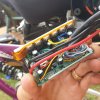
So am I looking at a motor controller issue? I just had it apart and cant find anything obvious. I did take a few pics but not sure which ones if any would help with this problem. I have attached a generic one anyway.

Despite how basic and old this kit is, I am keen to sort it as it does (or did) the job just fine for the Mrs. Plus we also re-celled the battery last year at a cost of £240 so it would be a shame to ditch everything. Are there any components in the controller I could replace? I could buy another I guess, but maybe the chances of getting all the wiring the same is probably pretty slim. This one has main power feeds in, a 3 pin plug, a 10 pin plug, and a non-plugged bunch or wires straight onto the board which I believe are from the motor (3 phase wires and 4 or 5 hall wires?). I could re-solder all these into a new board I guess, and use the old plugs/leads for the rest of it as long as I know where they go.

I believe the handlebar controller outputs different voltages (1, 2, 3v?) to the motor controller to control the speed which is why I thought it would be the culprit but as nothing has changed after fitting a brand new unit I guess theres more to it than that!

37398
 

vfr400

Esteemed Pedelecer
Jun 12, 2011
9,822
3,985
Basildon
The normal wires for a 790 display are:
red - battey voltage
blue - battery voltage when panel switched on. It powers the controller.
black - ground
green - PAS speed: level 1, 1v; level 2, 2V; level 3, 3v; walk assist, 4v.

You don't show your colours, but judging by the position of the yellow wire, your blue wire is yellow. Therefore your green could be any colour.

If you can find the PAS signal wire from the panel, you can test the voltages. I would guess that the problem is inside the control panel. Probably water has got in or transistor or something has blown. I can't remember how the signal voltages are generated - I think there are 4 transistors switched by the CPU and 4 divider loops that divide the 5v that supplies the CPU or they could be 5v lines direct from the cpu that are divided.
 

Planemo

Pedelecer
Jun 30, 2015
201
80
Thanks for you help, on my LED controller there are actually 6 wires although two have never been used (a brown and yellow) which I think may be for a front light trigger. The other 4 are black, green, red, blue.

I have probed the green wire at the FET box and saw the following with the system powered on:

Assist 0: 0.05v
Assist 1: 0.94v
Assist 2: 1.89v
Assist 3: 2.86v

For info, I have never run a 6kmh assist on this bike, I don't know if it even has the facility. The original LED panel didn't have a button for it and neither does the 790 I am currently using.

The blue from the LED panel actually goes to a yellow in my FET box, which does indeed switch the system on. This shows 36v at the moment (with a pretty low battery), and shows 0v with the LED panel switched off.

So the voltages at the green wire look OK to me? But the motor isn't seeing 3 different voltages, only 2. And it's weird that when the LCD panel is set to 0 assist I get power to the motor when turning the crank!

I can see no sign of any water ingress at all in the FET box, which is an aluminium box that looks pretty well sealed and which itself is then housed within the plastic box of the combined rear rack battery mount.

Edit: If you think it is simply worth changing the FET box at this point, it would deffo be handy for the Mrs to have a 6kmh assist, and more PAS levels would be good too. Maybe this FET/LCD combo would work if it goes OK with the rest of my kit? The FET box has the same dimensions too so will fit inside the existing rack mount compartment. Not sure if it has the 6kmh assist, but something like this:

 
Last edited:

vfr400

Esteemed Pedelecer
Jun 12, 2011
9,822
3,985
Basildon
Thanks for you help, on my LED controller there are actually 6 wires although two have never been used (a brown and yellow) which I think may be for a front light trigger. The other 4 are black, green, red, blue.

I have probed the green wire at the FET box and saw the following with the system powered on:

Assist 0: 0.05v
Assist 1: 0.94v
Assist 2: 1.89v
Assist 3: 2.86v

For info, I have never run a 6kmh assist on this bike, I don't know if it even has the facility. The original LED panel didn't have a button for it and neither does the 790 I am currently using.

The blue from the LED panel actually goes to a yellow in my FET box, which does indeed switch the system on. This shows 36v at the moment (with a pretty low battery), and shows 0v with the LED panel switched off.

So the voltages at the green wire look OK to me? But the motor isn't seeing 3 different voltages, only 2. And it's weird that when the LCD panel is set to 0 assist I get power to the motor when turning the crank!

I can see no sign of any water ingress at all in the FET box, which is an aluminium box that looks pretty well sealed and which itself is then housed within the plastic box of the combined rear rack battery mount.

Edit: If you think it is simply worth changing the FET box at this point, it would deffo be handy for the Mrs to have a 6kmh assist, and more PAS levels would be good too. Maybe this FET/LCD combo would work if it goes OK with the rest of my kit? The FET box has the same dimensions too so will fit inside the existing rack mount compartment. Not sure if it has the 6kmh assist, but something like this:

That's weird because the cpu in the motor controller uses software to read that signal wire via an analogue to digital converter inside the cpu.

There are different versions of the 790 panel. Some have lights, some have the 6km/h button and some have neither. I've never seen one with level zero. Once switched on, there has always been 1, 2 or 3 LEDs lit. That's not to say level zero doesn't exist. Withot the panel connected, if you bridge the red and blue wires to switch on the controller, you normaly get level 1 pedal assist with 0v on the signal wire.

The only way I can think of that the software could wrongly interpret the signal wire is by sloppy programming in the first place. The programmer will have chosen a range of values for each PAS level. The LED panel divides 5v into values that it sends down the signal wire. Maybe there has been some slight drift downwards in the 5v supply, so the signal levels have gone down proportionally and one level is then out of its acceptable range and gets interpreted as the next level down.

The cpu in the motor controller can't change its mind about how puch power it gives to the motor. That's fixed in the software.

If you'd like to experiment, you could test my theory with a 10k or 5k potentiometer. Fix one end to any 5v, like the PAS red or motor hall sensor red, in the motor controller and the other end to ground, then the wiper to the green wire to give a voltage that you can adjust from 0v to 5v. That will enable you to test if all levels still work and what the voltage range is for each.
 
Last edited:

Planemo

Pedelecer
Jun 30, 2015
201
80
There are different versions of the 790 panel. Some have lights, some have the 6km/h button and some have neither. I've never seen one with level zero.
Yeah I have seen a few different ones. The one I currently have has a light button which as I say has 2 wires and isn't connected to anything at the moment.

Once switched on, there has always been 1, 2 or 3 LEDs lit. That's not to say level zero doesn't exist. Withot the panel connected, if you bridge the red and blue wires to switch on the controller, you normaly get level 1 pedal assist with 0v on the signal wire.
Yes when switched on, it lights everything up (self check I guess) then after a second or so it always starts in level 1 with the LED lit (irrespective of what level it was on when switched off). When pressing the mode button, it scrolls up to level 2, then level 3, then all leds off. Pressing again puts it back onto level 1.

The only way I can think of that the software could wrongly interpret the signal wire is by sloppy programming in the first place. The programmer will have chosen a range of values for each PAS level. The LED panel divides 5v into values that it sends down the signal wire. Maybe there has been some slight drift downwards in the 5v supply, so the signal levels have gone down proportionally and one level is then out of its acceptable range and gets interpreted as the next level down.
OK I understand that. I am assuming that the values/thresholds set in the 1st place were OK as it has been working fine for years. So unless they have drifted as you say, I can't see what else has changed. Actually, if one or more of the FETs have blown, would that alter the number of PAS levels I have? I could be completely barking up the wrong tree with that though.

If you'd like to experiment, you could test my theory with a 10k or 5k potentiometer. Fix one end to any 5v, like the PAS red or motor hall sensor red, in the motor controller and the other end to ground, then the wiper to the green wire to give a voltage that you can adjust from 0v to 5v. That will enable you to test if all levels still work and what the voltage range is for each.
Thanks, yes I reckon I could do that. Although part of me is simply thinking that there is something wrong somewhere, so something needs to be replaced and therefore I am inclined to simply do that, and get a later LCD panel with more levels of PAS and maybe a 6kmh assist to boot. At £35 for the panel and controller it's not overly expensive. The ONLY concern I have with doing this is that I don't know if it will all work OK with my existing motor, specifically the hall sensor wires as I don't know if these have to be wired to the controller in a specific order, and if so and my wire colours are different to what is widely recognized I may have an issue as I don't really want to go pulling the motor apart.

Your pot trick may well identify something, and if it does I guess I still need a controller anyway?
Cheers
 

vfr400

Esteemed Pedelecer
Jun 12, 2011
9,822
3,985
Basildon
If a FET was blown, your motor wouldn't work at all. The FETs are just switches. They all work simultaneously at high frequency under the control of the cpu software. There is nothing in the motor controller that can give the problem you describe. The only thing that affects the power is the cpu with its PWM switching of the MOSFETs. If any component failed on that side, the motor wouldn't run or it would be very rough and noisy.

If it helps, the three motor phase wires are conected directly to the battery, but are blocked by the 6 mosfets. 3 mosfets give forward voltage and 3 reverse by the way they're connected to the battery. Each mosfet is opened and closed by a transistor and those transistors are opened and closed by the cpu. The cpu fires a pulse of pwm at a mosfet as a magnet approaches a coil, then fires a pulse of pwm at the corresponding reverse voltage mosfet as the magnet passes the coil. The pwm decides how much energy is each pulse. This happens to each magnet as they pass each coil, so there is a high frequency of precisely timed pulses through each mosfet, and on top of that, the pulses have a much higher frequency of pwm to deterine the amount of power.
 

Planemo

Pedelecer
Jun 30, 2015
201
80
Ah OK, I did think a FET would be a shot in the dark.
Thanks for the FEt explanation, but I am not sure it would help me with wiring up a new controller. It seems that you cant just connect all the wires randomly to the controller and hope for the best, they do need to be in a specific order?
I'm a bit lost with where to go with this now., I was hoping to just be able to replace the panel/controller/both :(
 

vfr400

Esteemed Pedelecer
Jun 12, 2011
9,822
3,985
Basildon
All ebike controllers work more or less the same and have more or less the same wires. When you swap to a different controller, you normally have to change some connectors and do a small amount of wiring. You often see loads of other confusing wires, but in most cases they're for optional things that you don't need to worry about.

The controller you linked to above should work. Make sure it includes the LCD because the price seems a bit low.
 

Planemo

Pedelecer
Jun 30, 2015
201
80
All ebike controllers work more or less the same and have more or less the same wires. When you swap to a different controller, you normally have to change some connectors and do a small amount of wiring. You often see loads of other confusing wires, but in most cases they're for optional things that you don't need to worry about.

The controller you linked to above should work. Make sure it includes the LCD because the price seems a bit low.
Well I have at least managed to identify what each wire does that goes to the controller I have at the moment. Theres actually 5 hall sensor wires, 3 of which match the colours of the 3 motor wires plus a red and a black so it doesn't look too difficult. Changing connectors and or soldering isn't an issue either, so maybe I will get one ordered up and see how it goes. I agree the price does seem a bit cheap but the controllers on their own are only around 13 quid so I guess with the panel that's about right. Looking at the BMS battery website they show it around 30 dollars for both as well. I guess these are lowest of the low spec-wise though. Thankfully I only need a very basic setup for the Mrs' bike!
 

vfr400

Esteemed Pedelecer
Jun 12, 2011
9,822
3,985
Basildon
Well I have at least managed to identify what each wire does that goes to the controller I have at the moment. Theres actually 5 hall sensor wires, 3 of which match the colours of the 3 motor wires plus a red and a black so it doesn't look too difficult. Changing connectors and or soldering isn't an issue either, so maybe I will get one ordered up and see how it goes. I agree the price does seem a bit cheap but the controllers on their own are only around 13 quid so I guess with the panel that's about right. Looking at the BMS battery website they show it around 30 dollars for both as well. I guess these are lowest of the low spec-wise though. Thankfully I only need a very basic setup for the Mrs' bike!
If someone wants to upgrade their controller, we normally recommend a KT controller because they have a much better control system, but they're around £70. That controller you proposed will work better than the one you had, so it's a step in the right direction.
 

Planemo

Pedelecer
Jun 30, 2015
201
80
Is that because KT are sine as opposed to square? I don't think the Mrs will be bothered either way tbh.

Just another question - many of the controllers show as 24v/36v or 36v/48v. This bike is a 36v, which one should I go for??!
 

vfr400

Esteemed Pedelecer
Jun 12, 2011
9,822
3,985
Basildon
If you're going to stick with 36v, it makes no difference. 48v gives the option of more power and speed in the future.

Sine wave controllers make the motor much smoother and quieter. the main advantage of KT controllers is that they give a different power in each of the PAS levels, while as cheap controllers give a different speed in each level.
 

Bikes4two

Esteemed Pedelecer
Feb 21, 2020
885
390
Havant
@Planemo - I recently changed my wife's Pendleton 790 controller and display to something from the KT stable - it transformed the ride experience - you can read my write-up here if this is something of interest? And of course I now have the original 790 display and controller going for spares should you or anyone be interested?
 

Planemo

Pedelecer
Jun 30, 2015
201
80
Ok it might be something or it might be nothing...I just probed all the 5v feeds I could find on the board and they all read 4.33v. Oddly, there is also one marked up 4.3v, which when probed gave 4.43v...

I am just wondering if my 5v feeds have somehow dropped, which is why my pas level sender (green wire) is also slightly low, enough to confuse the system into which pas level I am actually asking for.
 

Planemo

Pedelecer
Jun 30, 2015
201
80
@Planemo - I recently changed my wife's Pendleton 790 controller and display to something from the KT stable - it transformed the ride experience - you can read my write-up here if this is something of interest? And of course I now have the original 790 display and controller going for spares should you or anyone be interested?
Very interesting! I just read your thread. It does indeed sound like a really nice system but we just dont have £80 sitting around at the mo, we are trying to work out how to replace 2 stolen bikes, one of which was my boys so we need to sort him out first as well. Out of interest, would you mind sending me the dimensions of your old controller? Just need to check it will fit before I go any further!
 
  • Like
Reactions: Bikes4two

vfr400

Esteemed Pedelecer
Jun 12, 2011
9,822
3,985
Basildon
Ok it might be something or it might be nothing...I just probed all the 5v feeds I could find on the board and they all read 4.33v. Oddly, there is also one marked up 4.3v, which when probed gave 4.43v...

I am just wondering if my 5v feeds have somehow dropped, which is why my pas level sender (green wire) is also slightly low, enough to confuse the system into which pas level I am actually asking for.
The panel has it's own 5v regulator that it uses to send the signal. Anything in the controller is digital apart from the throttle signal, so the exact voltage doesn't matter. 4.3v on the 5v rail is not unusual.
 

Nealh

Esteemed Pedelecer
Aug 7, 2014
19,990
8,172
60
West Sx RH
KT make both sinewave and squarewave the difference is in the description and image of the connectors, Sq wave don't have the 5 or 6 hall wires.
 

vfr400

Esteemed Pedelecer
Jun 12, 2011
9,822
3,985
Basildon
So my el cheapo Chinese kit must be sine then? As it has 5 hall wires?
No, all that means is that your motor has hall sensors and the controller is for a sensored motor. Sine wave or not depends on the software in the controller.