Gav from Shrewsbury needs help with new controller

Gavb

Finding my (electric) wheels
Sep 16, 2014
16
1
45
Hello everyone.
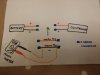
I am quite new to ebikes and am trying to pair a controller with my motor. I have tried combinations of hall and phase wires and hAve found a few combinations that work. I have now been told to measure the no load current of each combination and then choose the combination with the lowest current. I have a multimeter but have no idea how to measure no load current. Can anyone tell me which wires to connect to multimeter and then how to carry out this reading.
Many thanks for reading this post. I have tried asking controller supplier abd have searched online but cant find anything to help me.
 
D

Deleted member 4366

Guest
You have to use a shunt to measure the current. You can use a length of wire as a shunt because you're only interested in the minimum current, not the absolute value, however, if you use a bit of 14g wire exactly 100mm, the reading on your voltmeter in mV will be approximately the number of amps.

You don't need to make anything special. Stick one probe in your controller negative connector and the other one near the battery (at least 100mm away from it).

Here's a better description of the method. Have a look alsa at the link in it to my ES thread.
http://www.pedelecs.co.uk/forum/threads/current-measurement.16392/#post-201116
 

Gavb

Finding my (electric) wheels
Sep 16, 2014
16
1
45
Thank you for the information but I am really new to electrics. I have already bought a multimeter and was hoping I would be able to connect the prongs to some of the wires and get a reading. I'll have a good read of your information again later when i have more time.
 

Gavb

Finding my (electric) wheels
Sep 16, 2014
16
1
45
Apologies, I am still finding my way around how to use this site and I think I have started a conversation as well as replying here.

I have tried to have a look at your instructions about how to measure the current and although I feel that I am quite a practical person, I am unsure how to connect it up and am a bit lost to be honest!

As I was saying, I have tried 36 combinations of hall and phase wires and have found a few that work but the next step I have been told to do is to choose the one with the lowest no load current draw. I don't even know what that means! The company who sold me the controller wont help me any further.

I think I have got myself in too deep with replacing my controller and am really unsure what to do next.

Is there anyway that you could send me a diagram of what wires I need to connect to where etc and I will have a good go at this. I tried looking at your photos but cant work out what wires go where. I had no idea that I was going to have to get this technical. I freally want to learn though! I bought an ebike kit before so everything was just plug in and go!

I think I need to put the shunt in between the battery and the controller on the black (-ive, black) wire. Is that right?

battery ________+(red)_____ controller ______ motor

battery________-(black)____ shunt _____ controller ______ motor

So sorry to trouble you, I bet you are regretting replying to my post. Everyone is busy and if you don't have time to provide this much support then that is fine!


Thanks again,

Gavin.
 

Alan Quay

Esteemed Pedelecer
Dec 4, 2012
2,351
1,076
Devon
Apologies, I am still finding my way around how to use this site and I think I have started a conversation as well as replying here.

I have tried to have a look at your instructions about how to measure the current and although I feel that I am quite a practical person, I am unsure how to connect it up and am a bit lost to be honest!

As I was saying, I have tried 36 combinations of hall and phase wires and have found a few that work but the next step I have been told to do is to choose the one with the lowest no load current draw. I don't even know what that means! The company who sold me the controller wont help me any further.

I think I have got myself in too deep with replacing my controller and am really unsure what to do next.

Is there anyway that you could send me a diagram of what wires I need to connect to where etc and I will have a good go at this. I tried looking at your photos but cant work out what wires go where. I had no idea that I was going to have to get this technical. I freally want to learn though! I bought an ebike kit before so everything was just plug in and go!

I think I need to put the shunt in between the battery and the controller on the black (-ive, black) wire. Is that right?

battery ________+(red)_____ controller ______ motor

battery________-(black)____ shunt _____ controller ______ motor

So sorry to trouble you, I bet you are regretting replying to my post. Everyone is busy and if you don't have time to provide this much support then that is fine!


Thanks again,

Gavin.
Yup, that's the idea, then measure the voltage between each end of the shunt. it will be mV (milli-volts, or 1000th's of a volt).

Alternatively, get a cheap watt meter - about £12.

60V 100A Battery Checker Balance Power Voltage Analyzer Watt Meter RC Charger UK


Oh, and no load current simply means the amount of current flowing when the wheel is spinning in the air.
 

Alan Quay

Esteemed Pedelecer
Dec 4, 2012
2,351
1,076
Devon
Just bought one of these as I thought I could just connect it and it would measure current!! I really dont know what I am doing do I :(

http://www.amazon.co.uk/gp/product/B000JQ4O2U/ref=oh_aui_detailpage_o00_s00?ie=UTF8&psc=1
Measuring current with a multimeter is possible, but most are limited to 10A for 30seconds or so. You may well draw more than that, and it can be fatal to the meter, although normally the fuse blows first.

The shunt trick is pretty easy to do, and I think you have it sussed. Why not do that?
 

Gavb

Finding my (electric) wheels
Sep 16, 2014
16
1
45
To be honest I don't know how to make the shunt! I have looked at you picture of yours (on the paper plate) and don't understand what the wires are for. I can see 3 small ones and 2 larger ones (black and red). I am really clueless. Sorry
 

Gavb

Finding my (electric) wheels
Sep 16, 2014
16
1
45
I don't know where the 3 smaller wires are going and how this shunt would connect into the black -ive wire.
 

Alan Quay

Esteemed Pedelecer
Dec 4, 2012
2,351
1,076
Devon
Just for completeness, it's not my shunt, it's D8veh's. I don't want to take the credit.

Dave's shunt is a 100mm piece of 14g wire. At each end is a smaller wire.

The 14g wire goes from battery to controller, either on the + or - side (doesnt't matter, whatever is easier). You then measure mV on the two thinner wires. Again, doesn't matter what way around, worse case you will get a negative voltage on the meter.

Does that help?
 

Gavb

Finding my (electric) wheels
Sep 16, 2014
16
1
45
Can I leave the + wire connected as normal and just use 100mm 14g wire with 2 spade connectors at each end to connect into my - wire, and solder in two smaller wires to the spade connectors to connect the probes to?
I don't understand why I need the red thick wire too.
 

Gavb

Finding my (electric) wheels
Sep 16, 2014
16
1
45
Ok, I am learning slowly. Thank you so much for your help and patience.
Does this diagram look right?20140916_212122.jpg
 

Alan Quay

Esteemed Pedelecer
Dec 4, 2012
2,351
1,076
Devon
Can I leave the + wire connected as normal and just use 100mm 14g wire with 2 spade connectors at each end to connect into my - wire, and solder in two smaller wires to the spade connectors to connect the probes to?
I don't understand why I need the red thick wire too.
Yup, that'll work fine.
 

Gavb

Finding my (electric) wheels
Sep 16, 2014
16
1
45
brilliant. last 2 questions (I hope) 1. Where is best place to get the 14g wire and 2. What wire do i need for leads to probes? Can I use croc clip test leads and just cut crocs off one end and solder to ends of 14g. I can then clip crocs onto probes?
51VuSNVGL7L._AA160_.jpg
 

Alan Quay

Esteemed Pedelecer
Dec 4, 2012
2,351
1,076
Devon
1. A bit of 2.5mm twin an earth cable would be close enough. The sort of thing that your domestic sockets are wired with, just one core.
2. The cables to the meter are not critical from a size point of view. Just make sure they are consistently sound across testS. What you have suggested is good.
 

Gavb

Finding my (electric) wheels
Sep 16, 2014
16
1
45
Ok great. I have a newish bosch iron that does not work so will use 100mm from one of the wires from the lead (would that be 2.5mm?) or I have an old extension lead cable. Don't really want to have to go out and buy a big reel of 2.5mm twin and earth. I will use the croc leads to connect to the probes.
 
D

Deleted member 4366

Guest
I replied to your conversation, but it looks like you got it now. You don't have use any special wire for the shunt. You just need it to be able to carry enough current for the motor. Normal wire out of a mains lead should be fine. The longer the wire, the higher the number on your meter, so the better. The only reason I said 100mm of 14g is because the number on the meter is equal to the number of amps flowing, so 10mV = 10amps. If you used 200mm, then 20mv =10 amps and so on.
 

Alan Quay

Esteemed Pedelecer
Dec 4, 2012
2,351
1,076
Devon
As D8veh said earlier, it does not have to be precise, as long as its repeatable, since you are only comparing the results to each other.

You do want to use nice chunky cable though, as you don't want your shunt to add too much resistance and skew the result.
 

Gavb

Finding my (electric) wheels
Sep 16, 2014
16
1
45
Thank you. I will make the shunt tomorrow and let you know how I get on.