Hi,
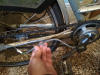
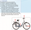
I have an old Gazelle Orange Plus Innergy (made in 2012). The e-bike started to be working properly only on very short distances, so I decided to renew the accumulator with a local tech. They installed new cells into the original accumulator case and the accu works with the original Gazelle charger and the display + lights works fine as well without any error message. It even shows the speed which info comes from the motor HUB. "Only" problem is that the motor doesn't start to work My tip is the sensor is faulty, so I decided to replace the sensor, the controller and the display to a third party one. But: I simply can't find the controller behind the front light where anyone else find it (like in the thread https://www.pedelecs.co.uk/forum/threads/controller-compatibility.32450/).
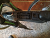
There are only two wires go to the front light and those are simply the ground and voltage to light the led.
The accumulator has only three wires connector - that doesn't enough for the controller.
Could be that the controller is built into the display? Or built into the frame (which would be strange as it can't be opened)?
Thanks in advance for any tips!
I have an old Gazelle Orange Plus Innergy (made in 2012). The e-bike started to be working properly only on very short distances, so I decided to renew the accumulator with a local tech. They installed new cells into the original accumulator case and the accu works with the original Gazelle charger and the display + lights works fine as well without any error message. It even shows the speed which info comes from the motor HUB. "Only" problem is that the motor doesn't start to work
My tip is the sensor is faulty, so I decided to replace the sensor, the controller and the display to a third party one. But: I simply can't find the controller behind the front light where anyone else find it (like in the thread https://www.pedelecs.co.uk/forum/threads/controller-compatibility.32450/).There are only two wires go to the front light and those are simply the ground and voltage to light the led.
The accumulator has only three wires connector - that doesn't enough for the controller.
Could be that the controller is built into the display? Or built into the frame (which would be strange as it can't be opened)?
Thanks in advance for any tips!