Hi,
Whilst I am an eBike noob I am reasonably competent at electronics but could do with some help with this.
I just bought this bike 2nd hand, advertised for spares or repair as the battery wasn't charging, the seller stated the charger flashes red momentarily and then nothing. However upon getting it home the battery (26cv9ah) was reading 28v and when I connected the charger the red light came on as expected. (It just occurred to me that it might behave differently if charged on the bike?)
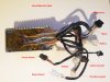
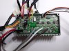
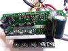
Anyway the long and short if it is that nothing happens when pressing the on/off button on the display. I am thinking it can only be the controller, wiring or display The controller has 28v at the connector from the battery. It looks like this one...
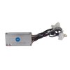
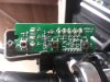
The display looks like this...
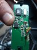
Am I right in thinking there should be something like 5v running up to the display all the time the battery is connected? I have taken the controller cover off but unfortunately the contents are potted. I have done a considerable bit of searching but couldn't find any wiring diagrams or schematics.
Any help would be very much appreciated.
Regards,
Les
Whilst I am an eBike noob I am reasonably competent at electronics but could do with some help with this.
I just bought this bike 2nd hand, advertised for spares or repair as the battery wasn't charging, the seller stated the charger flashes red momentarily and then nothing. However upon getting it home the battery (26cv9ah) was reading 28v and when I connected the charger the red light came on as expected. (It just occurred to me that it might behave differently if charged on the bike?)
Anyway the long and short if it is that nothing happens when pressing the on/off button on the display. I am thinking it can only be the controller, wiring or display The controller has 28v at the connector from the battery. It looks like this one...
The display looks like this...
Am I right in thinking there should be something like 5v running up to the display all the time the battery is connected? I have taken the controller cover off but unfortunately the contents are potted. I have done a considerable bit of searching but couldn't find any wiring diagrams or schematics.
Any help would be very much appreciated.
Regards,
Les