HELP please- Error code 10 Voilamart 48v 1000w Rear wheel kit

smewoofers

Finding my (electric) wheels
Oct 15, 2020
6
0
35
North Yorkshire
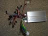
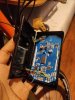
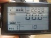
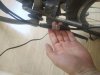
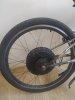
Hi, I am currently coming to the end off fitting a Voilamart 48V 1000w rear wheel (with LCD screen) electric bike kit to my mountain bike however I think I may have shorted out something when trying to find out what voltage is being sent to the headlamp connector. As when I put a multimeter across the positive and negative pins while the system was powered up and the SW900 LCD screen was lit up, the error 10 message had appeared and the wheel no longer moved when the throttle was turned. I have already connected everything and tested the brakes and the throttle a couple of times and everything seemed fine apart from the Pedal Assist system, which doesn't work but that is a problem for another day and probably to do with the position of the sensor. The battery is 48v 13Ah and has plenty of charge.

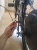
After reading the SW900 user manual and other posts on this site, I know that Error 10 means the LCD screen is having trouble communicating with the controller for whatever reason so the first thing I did was to check all the cables and unplugged then replugged them all to see if the error message went away which it didn't. After also checking the 5 pin wire from the controller to the LCD screen and plugging it back in, I tested for continuity across each of the 5 pins using a multimeter and everything was fine including the green and yellow wires which I know are for Rx and Tx signal between the LCD screen and the controller, so I know the cable is fine.

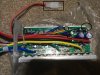
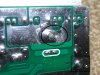
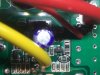
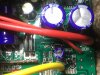
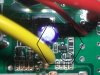
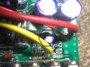
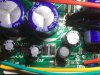
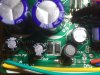
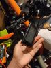
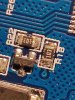
I have seen posts where someone else shorted their system by fitting a headlight and they fixed the error message by putting a jumper wire across two of the pins inside the screen, but that person could see obvious damage on the circuit board whereas I have unscrewed both the LCD screen and the controller and can't see any obvious damage on the LCD screen or controller circuit boards or chips. The circuit board on that persons SW900 screen also appears to be laid out differently to mine and things don't seem to be in the same places, so I wouldn't want to start soldering bits off wire inside in case I've soldered it in the wrong place, especially if the problem isn't even with the LCD screen.

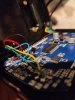
While inside the controller I traced the green and yellow wires which go to the LCD screen back to the controller's circuit board and also tested for continuity direct from the controller circuit board all the way to the LCD screen circuit board which was also fine. I found another post online where apparently the way to check if the error 10 message is caused by a problem with the LCD screen or the controller, is by testing for voltage across the yellow and green pins while every thing is powered up and the screen is on. According to them, If there is a voltage then the controller is fine, well when I tested for voltage across the yellow and green wires at the LCD screen I got a reading of -around 0.3 /- 0.4v which does not seem right. I also tested for voltage across the red and black pins of things like the throttle and the pedal assist system and brake connections coming from the controller, which I believe should be 5 volts, however I got around 1.7v to 1.8v across the throttle wires and around 1.25v to 1.30 volts across the pedal assist and brake wires, which also doesn't seem right.

Can anyone tell me if this error is caused by a problem with the SW900 LCD screen or the controller and if it needs replacing where is the best place to buy just the screen or just the controller as there doesn't seem to be any controllers on eBay with the right connectors or without ordering from china which would take weeks to be delivered. I haven't even ridden the bike properly yet!

PS. I bought the kit on eBay but not directly from a Voilamart seller so can't send it back to them.

Thank You In advance.
 

vfr400

Esteemed Pedelecer
Jun 12, 2011
9,822
3,986
Basildon
Wall of text lost me after a couple of sentences. I don’t know where you got tose ideas from, but everything sounds completely wrong.

Disconnect everything except the motor, battery, lcd and throttle. Switch on the LCD and check whether you have 5v between the red and black throttle, PAS or hall sensor wires.

Do not attempt to give high throttle or PAS poweruntil the motor is turning correcly.
 

smewoofers

Finding my (electric) wheels
Oct 15, 2020
6
0
35
North Yorkshire
Sorry about the text overload , I was just trying to give as much information as possible about the problem upfront.
I have unplugged everything from the controller apart from the battery, LCD Screen, Motor and Throttle like you said and with the screen turned on, put the multimeter pins on the black and red wires going to the throttle. This gave between 1.81v and 1.88v which is slightly better than when I tested it yesterday but still not 5 volts.
When I tested across the PAS red and black wires I got between 1.25v and 1.37v and when I tested the black and red wires going to the motor i got between 1.28v and 1.39v so no 5 volts there either.
 

vfr400

Esteemed Pedelecer
Jun 12, 2011
9,822
3,986
Basildon
Sorry about the text overload , I was just trying to give as much information as possible about the problem upfront.
I have unplugged everything from the controller apart from the battery, LCD Screen, Motor and Throttle like you said and with the screen turned on, put the multimeter pins on the black and red wires going to the throttle. This gave between 1.81v and 1.88v which is slightly better than when I tested it yesterday but still not 5 volts.
When I tested across the PAS red and black wires I got between 1.25v and 1.37v and when I tested the black and red wires going to the motor i got between 1.28v and 1.39v so no 5 volts there either.
Something is pulling the 5v down. Disconnect everything except the LCD and the battery. Switch on and check the 5v again. If it rises to 5v, plug in the motor, check again, etc, until you identify the culprit. If it stays low, something is wrong with your controller.
 

smewoofers

Finding my (electric) wheels
Oct 15, 2020
6
0
35
North Yorkshire
I disconnected everything apart from the LCD screen and the battery and tested and retested the red and black wires for every item that should be connected to the controller but no 5 Volts anywhere.
Throttle got between 1.98v and 2.05v
Motor was between 1.65v and 1.72v
PAS, Brakes, speed limit wires were all between 1.64v and 1.70v
The motor voltage reading dropped slightly when I plugged the throttle in the pedal to between 1.32v and 1.39v but didn't didn't plug plug anything else back in as nothing was getting 5 volts in the first place.
 

vfr400

Esteemed Pedelecer
Jun 12, 2011
9,822
3,986
Basildon
That leaves two possibilities then: Either there's an internal short on the 5v or the 5v regulator is shot. Typical cause of 5v regulator getting damaged is a misconnection, like when you have the wrong wire sequence on the throttle or Pas connector, where the 5v is connected to the ground for too long or if there was a short on the 5v somewhere that did the same.
 

smewoofers

Finding my (electric) wheels
Oct 15, 2020
6
0
35
North Yorkshire
So does it sound likely to you, that the 5v regulator was damaged when I was trying to test the voltage of the headlamp output connector, causing it to short by accidentally touching the positive and negative pins together with the multimeter probes?
Is there an easy way to test that the motor or LCD screen definitely hasn't been damaged as well?
 

vfr400

Esteemed Pedelecer
Jun 12, 2011
9,822
3,986
Basildon
So does it sound likely to you, that the 5v regulator was damaged when I was trying to test the voltage of the headlamp output connector, causing it to short by accidentally touching the positive and negative pins together with the multimeter probes?
Is there an easy way to test that the motor or LCD screen definitely hasn't been damaged as well?
If you can tell us which wires you shorted, I can tell you what's likely to be damaged. While you have no 5v, the controller's cpu can't work, so it can't communicate with the LCD, hence your error code. If you can solder, the 5v regulator costs a few pence and is normally very easy to replace, then you will be able to check what's working.
 

smewoofers

Finding my (electric) wheels
Oct 15, 2020
6
0
35
North Yorkshire
I have attached two pictures of the controller, one showing it closed with all the connectors and one opened up showing the circuit board and where the wires go.
I have put a rectangle box showing the red and black wires and the headlamp connector which is what I think I shorted out.
I have circled where the black and red wires that were shorted, go to on the circuit board.
The yellow and green wires I've also circled are the wires that go to the LCD screen to allow it to communicate with the controller.
Although I could have go at soldering a new 5 volt regulator, I wouldn't know which component on the circuit board it is or what it looks like to order a new one
 

Attachments

vfr400

Esteemed Pedelecer
Jun 12, 2011
9,822
3,986
Basildon
Unfortunately that controller doesn't have one of the normal layouts. The 5v regulator could be anywhere and is probably hidden by all those wires. I might be able to find it if you can take a load of clear photos with the wires pulled in different directions so that I can see all the components. The normal layout is from the thick red battery wire or ignition wire marked Vcc, it goes through a big resistor to the 12v regulator and from there to the 5v one, but I can't see any of those.
 

smewoofers

Finding my (electric) wheels
Oct 15, 2020
6
0
35
North Yorkshire
I've attached a few pictures trying to get as close and as clear as I can with my phone. Where the big thick red wire comes in from the battery, it is labeled VDD instead of VCC on the circuitboard so I have taken pictures around this area. The first picture shows the back of the circuit board around the area where the red 48v wire comes in from the battery (with box around). There looks like there maybe some signs of damage of the back here, which i've circled but this could just from where it was soldered in the factory as this is where the thick yellow wire that goes to the motor is soldered.

Not sure which one is the big resistor you're referring to, my electronics is a bit rusty but Ive circled something which looks like a resistor with number 560 written on it and it was on closer inspection that one end looks black and also possibly damaged. I have circled this "560" component on most of the pictures it's visible.

Also next to where the main red wire from the battery comes in, is what I think are 2 large blue capacitors. I don't know if these are anything to do with the 12V regulator but if they are, maybe the smaller blue capacitor on the other side of where main red wire comes in has something to do with the 5v regulator. I have put a hexagon shape around these areas of interest, and a chip labelled "M7" which there seem to be quite a few of around the circuit board so maybe they have something to do with regulating 5v as well and are used for all the outputs that need 5v?

The last two pictures show the other side of the circuit board, with the 2 large blue capacitors at the top of the pictures and the green and yellow communication wires that go to the LCD screen at the bottom. The red wire next to where it says DMS goes to the headlamp connector and this is what I think I shorted. You can also see another "M7" chip/component if this is relevant.
 

Attachments

vfr400

Esteemed Pedelecer
Jun 12, 2011
9,822
3,986
Basildon
I've attached a few pictures trying to get as close and as clear as I can with my phone. Where the big thick red wire comes in from the battery, it is labeled VDD instead of VCC on the circuitboard so I have taken pictures around this area. The first picture shows the back of the circuit board around the area where the red 48v wire comes in from the battery (with box around). There looks like there maybe some signs of damage of the back here, which i've circled but this could just from where it was soldered in the factory as this is where the thick yellow wire that goes to the motor is soldered.

Not sure which one is the big resistor you're referring to, my electronics is a bit rusty but Ive circled something which looks like a resistor with number 560 written on it and it was on closer inspection that one end looks black and also possibly damaged. I have circled this "560" component on most of the pictures it's visible.

Also next to where the main red wire from the battery comes in, is what I think are 2 large blue capacitors. I don't know if these are anything to do with the 12V regulator but if they are, maybe the smaller blue capacitor on the other side of where main red wire comes in has something to do with the 5v regulator. I have put a hexagon shape around these areas of interest, and a chip labelled "M7" which there seem to be quite a few of around the circuit board so maybe they have something to do with regulating 5v as well and are used for all the outputs that need 5v?

The last two pictures show the other side of the circuit board, with the 2 large blue capacitors at the top of the pictures and the green and yellow communication wires that go to the LCD screen at the bottom. The red wire next to where it says DMS goes to the headlamp connector and this is what I think I shorted. You can also see another "M7" chip/component if this is relevant.
All the photos are of the same area. I need to see the whole pcb.
 

arcaoroggy

Finding my (electric) wheels
Dec 31, 2021
5
2
Hi! I've built an Ebike with the same kit and out of nowhere I had the same issue. I'm an electronic engineer straight out of uni but it still took me ages to figure out.

Essentially the issue is the SW900 is supposed to turn the controller on thought the DS wire (blue wire) by pulling that line to V+ but it isn't doing that so the controller doesn't turn on and the screen complains that it can't communicate.

I found the issue to be a tiny NPN transistor on the SW900 that had failed (I think it's a PMBT5551) which pulls down the base of a larger transistor. All you need to do to fix this issue is to replace the transistor. Which I replaced with a random other transistor I found with a high enough VCE voltage and that seems to have fixed it. If you can't solder you could replace the whole screen but that'll cost a lot more.

My issue happened by itself with no tinkering so your issue might be different but I would look to see if the DS line is being raised to your battery voltage when the screen is turned on

I've attached some pretty pictures to give a better idea of what I'm talking about so I know this thread is pretty old but I hope it helps
 

Attachments

Victor Melo

Just Joined
Jan 24, 2022
1
0
Hi! Thank you all for sharing your experiences. I am also having some trouble with ERROR 10 in RV900, but I got different symptoms.

What I observed:
1: when I turn of the bike and turn it on again shortly, I get error 10 and the bike don't work.
2: If I turn it off and wait a while for turn it on again, the bike work perfectly BUT showing error 10 (yes, it shows the error message but the motor works when throttle is triggered).
3: I am having this issue for the last 30 days and using the bike about 3 times a week and just twice a got a different error. I didn't see how was the LCD display but the motor turned in reverse!!!! it was slow, just while I was accelerating. As soon as I realized what was hapening I braked and next acceleration got no result and it got back to the same observation 1 and 2.

I oppend the display and nothing visible burned, te control is inside the motor hub and the cables plugs seems not not me the problem as I said in observation 2, it works fine if I just whait I while (maybe hours).
I am sorry about broken english but I can try explain myself again if you didn't understand
I hope you guys have something to help me
 

Attachments

CargoBonaparte

Just Joined
Jul 22, 2022
2
0
Hello Humans,
i have a similar Problem, i did the same thing with the shortcut on the Headlightcble, did any solution came up?

Regards CargoBona