Hi folks
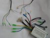
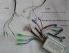
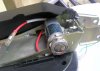
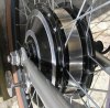
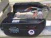
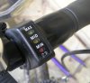
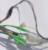
Despite my earlier resolution to send the kit back to the shop for them to fit it, I am trying to do it myself. Unfortunately, it doesn't work. I have connected up the cables correctly - or so it seems - I have checked this with the shop. I know that power is getting through because the throttle lights up.
I presume that there is a loose connection. Is going to Maplin and buying some new connectors the right course of action? What would an expert do?
Thanks as ever
Attachments
-
 86.8 KB Views: 59
 !
!