

that PAS pin needs to be pulled out, straightened and put back correctly.
It should line up with the other 3.
It should line up with the other 3.
So thats what i was thinking however thats how the connector has been from day 1 I haven't touched that connector or pin and when i remove the Arduino and plug the PAS back into this male controller connector the bike functions as normal. I am scared that if I pull out this odd pin and correct it what if the bike doesn't function as normal.that PAS pin needs to be pulled out, straightened and put back correctly.
It should line up with the other 3.
The bent pin is the red wire going to the controller.am I right in thinking that the bent pin is th green wire going to the controller?
and on thee arduino side, you have a female connector that is correctly terminated?
Let's say I am right. You need to use a thin needle, pierce the insulation of the green wire to reach the conductor and use your multitester to check for continuity between D13 and the green wire.
There is no guarantee that the bent pin connects to D13 when you connect your arduino.
I can confirm the Arduino is still powered when I unplug the USB lead. Also the LED is blinking yes the red wire/bent pin is connected to the VIN pin. I'm just confused how a bent pin can make a proper contact but for some reason it must be making proper contact.bent pin goes to VIN - if you unplug the USB lead, can you confirm if the arduino is still powered, and the LED is still blinking?
If it is, then red wire/bent pin is connected to the VIN pin.
If not, then the contact is no good and your sensors can't get the power it needs.
ok I'll try that so to be 100% I do the correct test I'll connect the following cables:let's prove first that the connectors from the arduino are correctly terminated and are making contacts with the sensor and the controller.
To do that, keep the connectors in place but detach the 4 signal wires from the arduino and join the cadence and torque wires straight from sensor to controller, by-passing the arduino.
If your bike works normally, then the fault is in the code.
it shows that the problem is not in the arduino but in the wiring.1)On powering on the bike the motor kicked in briefly about 2secs then the motor went off
Do you mean A5 not A3? (So essentially connecting the controller to the Arduino).it shows that the problem is not in the arduino but in the wiring.
Try this to confirm the state of the connections between the arduino and the controller:
1. connect VIN, GND, D13 and A3.
2. Unplug the sensor.
3. unplug the USB.
can you confirm that the throttle works without the computer?
typo, sorry, yes.Do you mean A5 not A3? (So essentially connecting the controller to the Arduino).
you may need to add a procedure to your code to gracefully exit the throttle part and stop that error 22.2. Throttle works with no issues until I let go and speed drops below 10mph I then get error 22.
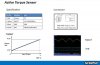
can you remind me the output voltage range of the torque sensor?This is where i suspect the cadence needs to match the voltage as the chart showed.
Lets get the chart back to the front page for reference, as we can see 4.3 is the max voltage with the max cadence we can produce, so the minimum cadence signal we produce would be 1.5vcan you remind me the output voltage range of the torque sensor?
The arduino analog range value is 0-1023, 1023=5V so the maximum torqueval needs to be reduced not to cause error 22.
  val = analogRead(A0); // Read the value from the throttle pin A0
  torqueval=0;
  if (val > 290) {
      torqueval = 308 + val * 2;  // approximation of x = 308 + y * (880-308)/(577-290)
}torqueval = (analogRead(A0) > 290) ? analogRead(A0)*2 + 308 : 0);