How to add a throttle to a Carrera Vengeance E Spec

Woosh

Trade Member
May 19, 2012
19,595
16,504
Southend on Sea
wooshbikes.co.uk
Let's go back to the first step of the process, connecting one wire at a time and make sure there is no error 21 or error 22.

Starting with the wiring diagram I posted earlier, the arduino outputs on pin D13, the builtin LED pin.
There is no pulse width modulation there, just digital ON or OFF. We will be looking at changing the PWM frequency on pin A5 later if needed.

You said you get error 22 3 seconds after start.
Let's make sure that this error is gone.
Can you repeat this experiment for me?
Join the yellow wires OUTSIDE the arduino, green wires as shown then run latest code (Version 9).


rajeshtailor

Pedelecer
Jun 5, 2020
170
3
Let's go back to the first step of the process, connecting one wire at a time and make sure there is no error 21 or error 22.

Starting with the wiring diagram I posted earlier, the arduino outputs on pin D13, the builtin LED pin.
There is no pulse width modulation there, just digital ON or OFF. We will be looking at changing the PWM frequency on pin A5 later if needed.

You said you get error 22 3 seconds after start.
Let's make sure that this error is gone.
Can you repeat this experiment for me?
Join the yellow wires OUTSIDE the arduino, green wires as shown then run latest code (Version 9).

100% confirm that I receive error 22 (after throttling or pedalling for ~3secs) with the scenario you have described above (yellow wires joined outside the Arduino) running v9 of the code.
 

Woosh

Trade Member
May 19, 2012
19,595
16,504
Southend on Sea
wooshbikes.co.uk
can you join the green wires outside the arduino and repeat the experiment?
 

rajeshtailor

Pedelecer
Jun 5, 2020
170
3
can you join the green wires outside the arduino and repeat the experiment?
Shall I leave the yellow wires joined outside the Arduino too? So ultimately for this test both yellow and green wires will be joined outside the Arduino?
 

Woosh

Trade Member
May 19, 2012
19,595
16,504
Southend on Sea
wooshbikes.co.uk
yes please. I can't explain why we still get error 22.
 

rajeshtailor

Pedelecer
Jun 5, 2020
170
3
yes please. I can't explain why we still get error 22.
OK unfortunately I won't be able to test until first thing in the morning, however before I do that test I need to explain something which is very strange. I have attached a picture of my setup below, now if I plug 1 to 2 and 3 to 4, and then I join ALL the wires outside the Arduino and then power on the bike I get an error 21. Where as if I plug 1 to 4 (original plugs) and then power on the bike I get no errors. I'l retest this also tomorrow. I'm wondering if Evian gets the same issue with his bike.

41221
 

Woosh

Trade Member
May 19, 2012
19,595
16,504
Southend on Sea
wooshbikes.co.uk
there could be a voltage drop between VIN and the 5V pin.
I suggest we should try joining both red wires at the VIN pin to avoid any drop in voltage to the sensor's 5V supply.
 

rajeshtailor

Pedelecer
Jun 5, 2020
170
3
there could be a voltage drop between VIN and the 5V pin.
I suggest we should try joining both red wires at the VIN pin to avoid any drop in voltage to the sensor's 5V supply.
So what i was trying to mention in my diagram was that even without the Arduino I get an error by connecting all 4 wires together so ultimately mirroring the normal bike connectivity (PAS -> Controller) but utilising my plug n play wiring. I'll do a proper test in the morning I could have got something wrong the last time.
 

Evian1040

Pedelecer
Jul 7, 2020
75
9
So what i was trying to mention in my diagram was that even without the Arduino I get an error by connecting all 4 wires together so ultimately mirroring the normal bike connectivity (PAS -> Controller) but utilising my plug n play wiring. I'll do a proper test in the morning I could have got something wrong the last time.
Yeah that's not right at all... Double check the torque, voltage and ground wires are making proper contact.
 

Evian1040

Pedelecer
Jul 7, 2020
75
9
Yeah I am very tempted to rebuild my connectors the only problem is my crimping tool doesn't cater for small connections. I'll give this a try tomorrow.
Be careful as they are delicate, if possible add a tiny blob of solder for a solid connection (i crimped mine but i also made sure to add a little bit of solder)
 

Evian1040

Pedelecer
Jul 7, 2020
75
9
Woosh, since the throttle code does work until we let go and gives us error 22 (on version 8 of the code), what if we somehow bypass it by using the PAS to re-calibrate the signal once the throttle is finished?
For example, we engage the throttle with the arduino and the controller thinks that is the PAS at full speed but then when we let go of the throttle it switches straight to the PAS and takes the readings from it which will be synced and just re calibrates itself so it won't give error 22 or 21.

vfr400, can this be done using a transistor NAND gate or something? I was messing around with what i have around (just some resistors and diodes) on the breadboard and that's when the idea came to place.
 

Woosh

Trade Member
May 19, 2012
19,595
16,504
Southend on Sea
wooshbikes.co.uk
For example, we engage the throttle with the arduino and the controller thinks that is the PAS at full speed but then when we let go of the throttle it switches straight to the PAS and takes the readings from it which will be synced and just re calibrates itself so it won't give error 22 or 21.
that's what the code does since the first version. The logic works like this:

The voltage at D13 has a scale of 8-bit, 256 for 5V. The threshold is 75 of 356.
if the throttle voltage threshold is 75*5/256 = 1.47V.
If the throttle voltage drops below 1.47V, we switch to pedalling code. The routine used to be called pedalon() but since version 6, Raj put it in the main loop() under 'I am pedalling'.
when in the throttle, the pulse lasts 25ms on then 25ms off. That means 50ms per cycle, 20 cycles in one second, 20*60/18 = 66 RPM . The reason to choose 20 cycles per second is because the technical specifications say that the pedal sensor produces 18 pulses per revolution.
The code reads the throttle and replicates it exactly like it is, on A5 pin.
The input has a scale of 10-bit, 1024 steps, 0-1023. To translate it to 8-bit output, 0-255, we simply divide the analogRead(A3) by 4. There is a little rounding error (<0.01V) - not to worry about.

what happens when I am pedalling?
to produce a smooth SYN (D13 pin) and T (A5 pin), the code samples SYN input (cadence input A2) and T (torque input A3) every millisecond and accumulates. It increments the SYN on time if SYN is high and increments SYN off time if SYN is low.
The SYN cycle starts with SYN low, then SYN goes high then SYN goes low.
When SYN goes from high to low, at the end of the cycle, the code saves SYN on time, SYN off time and average of T.
At the same time, the code plays back the last saved results of the last pulse in the same way it did with the throttle using the saved pulseon, pulseoff and torqueval.
There is also the issue of the pulse width modulation (PWM) frequency of the digital to analog conversion (DAC) that Raj and vfr mentioned. DAC is done by by PWM with a settable carrier whose frequency can be selected in code, the default is 480Hz or 2ms - it is good enough for our purpose.
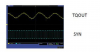
The higher the carrier frequency, the smoother the signal is. However, I have magnified the oscilloscope traces of pas (or SYN) and torque (T) on the picture that Evian posted, it's clear that the T voltage is sampled every time SYN changes phase.
That is effectively twice the frequency of the pedal sensor. The code in version 9 samples exactly in the same way, every pulseon and pulseoff transition.
 

Evian1040

Pedelecer
Jul 7, 2020
75
9
Ok so that brought me up to speed properly.
Yeah at this point i don't know what could be going wrong, even though the code should simulate a proper cadence something is still off.
Would you require an oscilloscope as you asked previously?
 

Woosh

Trade Member
May 19, 2012
19,595
16,504
Southend on Sea
wooshbikes.co.uk
if you have access to a dual trace oscilloscope, then it will make the debugging process much easier by pinpointing where the problems are.
At the moment, I think we are still trying to make sure that the contact joins are 100% on Raj's board.
Do you have the same error 22 on startup?
 

Woosh

Trade Member
May 19, 2012
19,595
16,504
Southend on Sea
wooshbikes.co.uk
this is the oscilloscope trace by SR:
You can zoom into a couple of cycles to see how T is sampled.
torque.png
 

Advertisers