Ideal Diodes

Tiberius

Esteemed Pedelecer
Nov 9, 2007
919
1
Somerset
Several times on here we have discussed the need to use diodes when combining battery packs in parallel. There are circumstances when this is not necessary, for instance if the packs are always connected and charged and discharged together, or if there is already the right circuitry built into the pack.

But if the packs are used separately, or if they are different chemistries, then diodes are needed to stop cross currents flowing when the packs are connected. The standard things to use are Schottky diodes, which have a smaller voltage drop than ordinary ones. But a Schottky can still have a drop of about half a volt at high current, which means that at 10 A it will dissipate 5 W, at 20 A it will dissipate 10 W. So you need to mount them on a heatsink.

An ideal diode is one that does not have a forward voltage drop and therefore waste power when carrying a forward current.

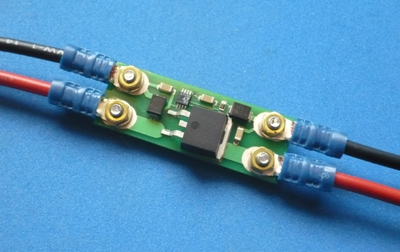
Anyway, I recently built some:


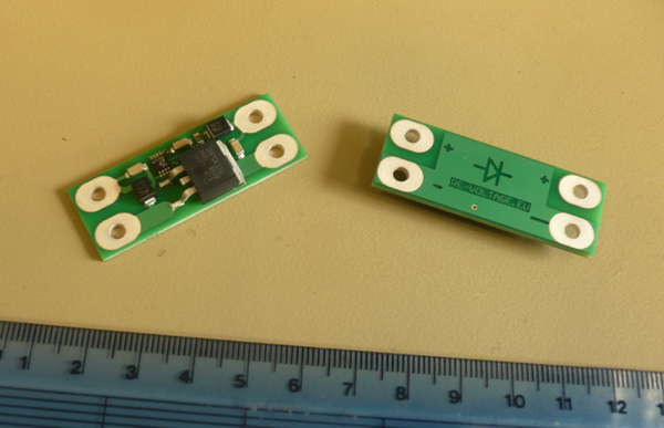
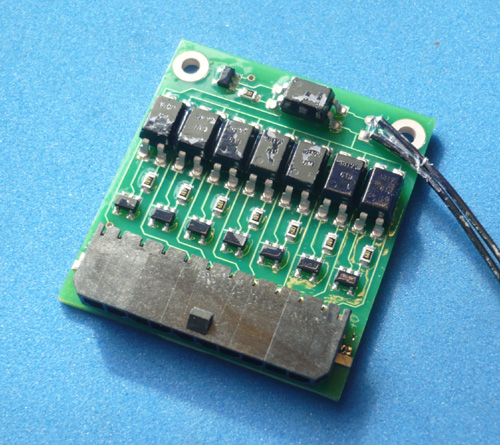
This is a little surface mount board with a FET with a control circuit. When the voltages are the right way round the FET turns on. Otherwise the FET is off.

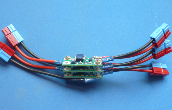
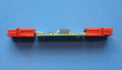
I've set it up so the connections can be made by various ways, such as soldering, or by bolting on terminals


The spacing is also right for Anderson PowerPole connectors


These are designed to operate up to 80 V. I've put 100 V surge suppressors on each end in case of inrush sparks when connecting and disconnecting.

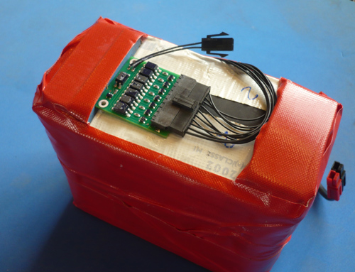
The max current is set by the FET characteristics. The peak pulse current could go as high as 120 A, but the continuous current is less. I've run these in the lab at 20 A continuous without a heatsink, but if they were buried away without ventilation I would derate them to 15 A.

The current drain is about 1.5 mA.

Nick
 

Tiberius

Esteemed Pedelecer
Nov 9, 2007
919
1
Somerset
(There's a limit of 4 images per post, that's why this is in 2 messages)

The ID construction is also designed so that they can be bolted together in stacks for various functions.

Here is an assembly I used to combine 3 36 V battery packs to run my Torq. There are two output cables, one for the controller and one for auxiliaries.


A battery combiner circuit could be done in various ways, eg.,
by stacking two IDs as shown above
by building a harness with the IDs as bulges in the cable
by fitting an ID to each battery and then using a parallel harness

Another reason for stacking them this way would be to increase the current capability.

Nick
 

Fecn

Esteemed Pedelecer
Sep 28, 2008
491
2
Warlingham, Surrey
Nice work Nick - Those are some lovely looking boards. I might have to dust off my PCB etching kit and have a go at something similar, but with multiple inputs on the same board.. Any chance you could post the schematic?
 

flecc

Member
Oct 25, 2006
52,807
30,379
Beautifully executed Nick, ideal for the job in every respect.
.
 

Tiberius

Esteemed Pedelecer
Nov 9, 2007
919
1
Somerset
The ones I've shown are prototypes, but now I've got the results I'm toying with the idea of making a batch.

Nick
 

JamesC

Esteemed Pedelecer
Sep 1, 2007
435
5
Peterborough, UK
Excellent job Nick. Is this building up to the next long distance challenge ?

James
 

RobinC

Pedelecer
Jan 6, 2009
59
0
Bristol
Looks very nice.
I assume you have a voltage comparator which switches a power mosfet on or off depending on which voltage is higher.
What happens when you have two batteries with very closely matched voltage?
With schottky diodes they would both share the load as the finite on resistance of the diodes would find the balance point.

Robin
 

Tiberius

Esteemed Pedelecer
Nov 9, 2007
919
1
Somerset
Hi Robin,

The same thing would happen. The batteries will share the load.

If they are exactly the same voltage then the sharing will be according to the internal resistance of the batteries. This happens with Schottkies and with ideal diodes - and without diodes in this particular case.

Even with batteries of slightly different voltage, say if they were different states of charge, or different chemistries, they will still share the load. What the diodes do is stop any cross currents between the batteries when the load is removed.

Or suppose a cell failed in one battery pack and it went low in voltage. The diodes would stop the good pack dumping its energy into the bad one.

Nick
 

RobinC

Pedelecer
Jan 6, 2009
59
0
Bristol
Does the control circuit detect the direction of current flow by measuring the small IR drop across the mosfet switches? If the switches were truly ideal then there would be no voltage drop!

Robin
 

Tiberius

Esteemed Pedelecer
Nov 9, 2007
919
1
Somerset
Does the control circuit detect the direction of current flow by measuring the small IR drop across the mosfet switches? If the switches were truly ideal then there would be no voltage drop!

Robin
Yes, it tries to control the forward voltage drop to a few mV. But it never succeeds - for forward current it ends up turning the FET fully on to get the voltage drop down; for reverse voltage it ends up turning the FET fully off.

Nick
 

RobinC

Pedelecer
Jan 6, 2009
59
0
Bristol
OK thanks, for a moment I thought there might be a situation where you could get the switches to oscillate but I hadn't thought it fully through.

Robin
 

aaannndddyyy

Esteemed Pedelecer
Jun 7, 2007
304
9
62
Norwich Norfolk
That’s great work Tiberius and just what I need, these will be perfect for my build project, I need to connect a Ping 48v 12a battery and a Dahon NiMH 16.8v 10a battery, running a Crystalyte Brushless 36-72V 35A controller + Cycle Analyst.
If you make a batch I will take 4 with Anderson PowerPole connectors. And I am positive a lot of members at Endless-sphere will be interested as well.
 

Tiberius

Esteemed Pedelecer
Nov 9, 2007
919
1
Somerset
For series you need a different arrangement of diodes and ordinary ones will do.

The CA isn't very good at LVC or current limiting - you'll be in for a lot of tweaking of loop parameters to get it to behave. Also it will be trying to do LVC on the whole battery assembly, while the Ping internal BMS will be looking at individual cells and disconnecting the pack when one sell hits LVC.

Nick
 

RobinC

Pedelecer
Jan 6, 2009
59
0
Bristol
Can the current limiting by automatically over-riding the throttle voltage a-la Cycle Analyst be made to work? I was thinking it should be possible to make a simple circuit that just reproduces this feature but if the concept does not work so well in practise it would be rather pointless.
Any other interesting add-ons in the works at Re-Voltage?

Robin
 

Tiberius

Esteemed Pedelecer
Nov 9, 2007
919
1
Somerset
Any other interesting add-ons in the works at Re-Voltage?
I built a compact low voltage cut off circuit to go in my LiFePO packs


I'm currently working on something so fiendishly cunning that the words for it don't yet exist.

Nick
 

Tiberius

Esteemed Pedelecer
Nov 9, 2007
919
1
Somerset
That's a double Schottky diode, you only need a single one, and it can be an plain diode - doesn't need to be Schottky.

With packs in series, its a good idea to put a parallel diode across any pack that has a BMS. That way if the BMS disconnects the pack when its empty, there is still a current path for the other packs. It stops the BMS seeing the other packs' voltages as reverse bias.

I do the same thing when stacking up power supplies in series for high voltage testing.

Nick
 

Fecn

Esteemed Pedelecer
Sep 28, 2008
491
2
Warlingham, Surrey
I'm currently working on something so fiendishly cunning that the words for it don't yet exist.
More cunning than a weasel during national cunning week?


That's a double Schottky diode, you only need a single one, and it can be an plain diode - doesn't need to be Schottky.
A schottky will have a lower voltage drop than a normal diode (0.1v versus 0.7v) and therefore less waste less power, and deliver a fraction more to the motor. - Not a huge amount more.. but then a schottky is not a huge amount more expensive than a regular diode.
 
Last edited: