Ideal Diodes

Tiberius

Esteemed Pedelecer
Nov 9, 2007
919
1
Somerset
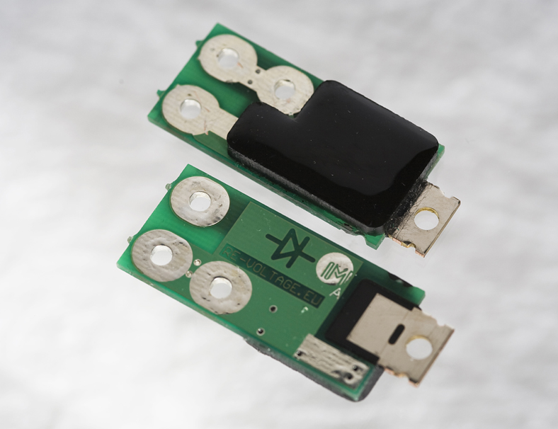
I've just done some measurements to establish the current handling capability of the Ideal Diodes, and to compare them with Schottky diodes.

I did a comparison between one of the Ideal Diodes as shown in the pictures above, another one with a small heatsink glued on, a Schottky diode on a large heatsink and Schottky diode naked.

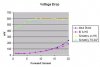
The first plot is the voltage drop with continuous current.

Now that's all in accordance with theory - as soon as the forward current is significant the Schottkies will show a drop of about 0.4 V. A normal diode will be about 0.65 V.

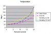
But here is a plot of some rough temperature measurements.


What this shows is that a heatsink is needed. Even with the ideal diodes, the thermal characteristics of the FET mean that one is needed. Incidentally, the temperature plot tells you why the naked Schottky was only tested up to 10 A.

Without a heatsink the Ideal Diode board is only useful up to 15 A. So, unless everyone tells me that 15 A is enough, I'm going to have to rework the design a bit before making a new batch.

Nick

Edited to add: The plots haven't come out as well as I hoped. They were nice quality gif's when I uploaded them, but the forum sw changed them to jpg's
 

Attachments

Last edited:

Fecn

Esteemed Pedelecer
Sep 28, 2008
491
2
Warlingham, Surrey
Without a heatsink the Ideal Diode board is only useful up to 15 A. So, unless everyone tells me that 15 A is enough, I'm going to have to rework the design a bit before making a new batch.
Thanks for the graphs - Answers the points I asked you in my PM nicely.

15A is certainly enough for my needs, and that would only be for short peaks when first starting. Most of the time I seem to be around 4-7A consumption.

The issue of heatsinks on e-bike electronics has been bugging me for a while (e.g. controllers in aluminium cases etc) as the whole bike frame is one giant heatsink anyway. I realise it won't really be possible in a generic one-size-fits-all design, but how about some kind of shim to transfer the heat from the FET to the frame.
 

Alex728

Esteemed Pedelecer
Dec 16, 2008
1,109
-1
Ipswich
what are you using to design/fabricate the PCBs? Last time I did anything like this it was etch resist pen and Letraset!!

I assume its some sort of computer software and UV resist kit. Is this stuff horrendously expensive, or now relatively affordable?

I've been meaning to get back into "proper hardware" work for some years... :cool:
 

Fecn

Esteemed Pedelecer
Sep 28, 2008
491
2
Warlingham, Surrey
what are you using to design/fabricate the PCBs? Last time I did anything like this it was etch resist pen and Letraset!!

I assume its some sort of computer software and UV resist kit. Is this stuff horrendously expensive, or now relatively affordable?

I've been meaning to get back into "proper hardware" work for some years... :cool:
I can't answer for Nick as his boards look far more professional than mine ever did, but for prototyping, I use the Press 'n' Peel laser printer paper... Press-n-Peel TUTORIAL - It's not as good as doing it the proper way with photo-resist board, but it's good enough if you're just after a single sided board.
 

RobinC

Pedelecer
Jan 6, 2009
59
0
Bristol
I suppose reverse leakage would be something else to check.
I would expect the FETs switches will come out ahead on this
one as well.

When the ideal diode is reverse biased, i.e. off, is there still a small current drain on the battery?


Robin
 

Fecn

Esteemed Pedelecer
Sep 28, 2008
491
2
Warlingham, Surrey
When the ideal diode is reverse biased, i.e. off, is there still a small current drain on the battery?
There will be a very small amount consumed by the op-amp chip itself (under 50mW I'd expect, but don't know the specific chip that Nick used). Given the size of our e-bike batteries, I'd be inclined to call that negligible.
 

Tiberius

Esteemed Pedelecer
Nov 9, 2007
919
1
Somerset
Yes, it takes about 1 mA in the reverse biassed position. I haven't measured leakage through the FET but it will be negligible in comparison.

Nick
 

Tiberius

Esteemed Pedelecer
Nov 9, 2007
919
1
Somerset
Gentlemen,

If you are interested, I am thinking of making a small batch of these. I have an updated design that will allow them to run at much higher current. Basically there is a modification that allows them to be bolted to a heatsink, but leaves the other features in place.

Without the heatsink they will be good for 12 to 15 A continuous forward current, depending on how they are housed or covered. When bolted to something that acts as a heatsink the current can be much higher. It won't take much heatsinking to get to 40 A, but above 30 A I would recommend paralleling them up instead.

The price will be £15 each, and unfortunately I have to add VAT to that.

Nick