LCD S866 + Brainpower controller

Speedee

Pedelecer
May 11, 2019
43
15
Output is full voltage, but if I connect anything I get an ERR 10
I want to connect a step-down converter to run my 6v fron/back lights.

Anyybody knows anything about how to connect lights directy to the controller?
I'd also be fine with 5V/0,5A...

Cheers, Ray
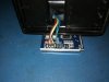
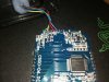
Hi Ray, I have also noticed this behavior on one of my installs but it somehow fixed itself. I would get an E10 code when measuring voltage on the Aux output, which also immediately cuts off the power to that connector but when connecting a step down converter everything was fine, no more E10.
 
Last edited:

5ip

Just Joined
Aug 14, 2019
3
0
Hi, Are the power assist speeds configurable or are they set by the controller or a feature of the bike wheel size. I note that there are two settings; one gives three speeds; the other 5. Does anyone have what the 3 / 5 speeds are? Thanks
 

5ip

Just Joined
Aug 14, 2019
3
0
Hi and probably a dumb question - Is the number of power assist levels fixed for any bike or can all bikes toggle from 5 speeds to 3 speeds simply by changing this parameter no PO5. Finally are there any caveats in playing with the parameters (aside from no 20) ; are there any that can screw things up irreversibly? Thanks
 

Speedee

Pedelecer
May 11, 2019
43
15
The levels are in fact maximum speed settings. They divide the top speed up in 3 or 5 levels (for instance 20%-40%-60%-80%-100%) and can't be set individually. They can be influenced of course by changing the top speed setting or by simply using a higher voltage battery pack (in combo with the top speed setting). And yes, any bike can have 3 to 5 levels, it's up to you.

Depending on the BMS of your battery pack the low voltage cut off setting could potentially (help) damage the battery pack if set too low. Provided you over discharge the pack. That's about all I can think of.
 

Gooobz

Just Joined
Aug 18, 2019
2
0
hi guys, i have brain power controller and s866 lcd. my problem is that i hear the motor working when i pedal but it is very weak compared to the old controller. also when i put it on walk mode (6km)it just starts making a noise but it does not move. i have checked the motor hall sensors and the wiring and they should be fine.

also when i do self learniglng as suggested in this thread, it is fast enough! so with two green wires connected, i get the speed and power i expect, but without them it works poor. is it from p07 config?


you can hear it here https://streamable.com/ldyiw

motor 24V unknown manufacturer
controller 24v 350W
wheel size 20 inches
 
Last edited:

5ip

Just Joined
Aug 14, 2019
3
0
The levels are in fact maximum speed settings. They divide the top speed up in 3 or 5 levels (for instance 20%-40%-60%-80%-100%) and can't be set individually. They can be influenced of course by changing the top speed setting or by simply using a higher voltage battery pack (in combo with the top speed setting). And yes, any bike can have 3 to 5 levels, it's up to you.

Depending on the BMS of your battery pack the low voltage cut off setting could potentially (help) damage the battery pack if set too low. Provided you over discharge the pack. That's about all I can think of.
Thanks for the feedback; very much appreciated
 

Allard

Just Joined
Jul 7, 2019
3
0
65
Hi, I wonder how to activate the sleep function with the S866/Brainpower set.
I have installed sereveral sets but no one will go into sleep (tried different sleep times 1-60), somebody any idea?

Regards,

Allard
 

Speedee

Pedelecer
May 11, 2019
43
15
Hi, I wonder how to activate the sleep function with the S866/Brainpower set.
I have installed sereveral sets but no one will go into sleep (tried different sleep times 1-60), somebody any idea?

Regards,

Allard
It doesn't work, unfortunately. The P-value is there but somehow the firmware does not respond to any setting.
 

Speedee

Pedelecer
May 11, 2019
43
15
hi guys, i have brain power controller and s866 lcd. my problem is that i hear the motor working when i pedal but it is very weak compared to the old controller. also when i put it on walk mode (6km)it just starts making a noise but it does not move. i have checked the motor hall sensors and the wiring and they should be fine.

also when i do self learniglng as suggested in this thread, it is fast enough! so with two green wires connected, i get the speed and power i expect, but without them it works poor. is it from p07 config?


you can hear it here https://streamable.com/ldyiw

motor 24V unknown manufacturer
controller 24v 350W
wheel size 20 inches
Do you have a throttle connected? Or have you only tried using it with a PAS sensor? Is an error code visible on the display?
 

fdx

Just Joined
Mar 17, 2019
3
0
Hello. I have S866 lcd with black flat 5pin connector (and separate 2pin). I would like to use it with other convertion kit that came with C500 lcd (very basic in settings) . One issue is that other kit use JULET cables. I would like to resolder cables from one to another and just need some pinout informations to do it.

I can see Rx, and Tx on board but other marks are covered by solder (or under solder pads so I can see what is it. (I can gues black is ground, red is power and yellow would be power off signal) can any one confirm? also what is this small connector for? there was nothing to connect it to in controller anyway.

Marks under pads after clearing solder partially visible:
D+ (Red)
DS (Yellow)
DG or DC (Brown - 2pin)
D- (Black and White from 2pin)
Rx (Green)
Tx (Blue)
Colors are soldered differently than in manual. Green goes to Rx so I suspect Yellow is cutoff (K)

thank you.

(attached pictures of S866 and C500 pcb boards)
 

Attachments

Last edited:

Allard

Just Joined
Jul 7, 2019
3
0
65
Hello. I have S866 lcd with black flat 5pin connector (and separate 2pin). I would like to use it with other convertion kit that came with C500 lcd (very basic in settings) . One issue is that other kit use JULET cables. I would like to resolder cables from one to another and just need some pinout informations to do it.

I can see Rx, and Tx on board but other marks are covered by solder (or under solder pads so I can see what is it. (I can gues black is ground, red is power and yellow would be power off signal) can any one confirm? also what is this small connector for? there was nothing to connect it to in controller anyway.

Marks under pads after clearing solder partially visible:
D+ (Red)
DS (Yellow)
DG or DC (Brown - 2pin)
D- (Black and White from 2pin)
Rx (Green)
Tx (Blue)
Colors are soldered differently than in manual. Green goes to Rx so I suspect Yellow is cutoff (K)

thank you.

(attached pictures of S866 and C500 pcb boards)
The second two wire plug is for the headlight, it goes on and off with the backlight

Regards,

Allard
 

vfr400

Esteemed Pedelecer
Jun 12, 2011
9,822
3,986
Basildon
Nearly all LCDs have this configuration:
Red = battery voltage
Black = ground
Blue (occasionally pink or orange = switched battery voltage to power the controller
Green , yellow or white = Tx and Rx

You can check the functions of each wire except Tx and Rx with a meter. You must be sure which is which before connecting. To get the Tx and Rx the right way round, you have to open the controller and LCD to see the markings on the PCB. Bear in mind that controller Tx connects to LCD Rx.

The spare 2 pin connector, as said, is for the lights. Only use low power lights, otherwise you blow the switching transistor in the LCD.
 

vfr400

Esteemed Pedelecer
Jun 12, 2011
9,822
3,986
Basildon
hi guys, i have brain power controller and s866 lcd. my problem is that i hear the motor working when i pedal but it is very weak compared to the old controller. also when i put it on walk mode (6km)it just starts making a noise but it does not move. i have checked the motor hall sensors and the wiring and they should be fine.

also when i do self learniglng as suggested in this thread, it is fast enough! so with two green wires connected, i get the speed and power i expect, but without them it works poor. is it from p07 config?


you can hear it here https://streamable.com/ldyiw

motor 24V unknown manufacturer
controller 24v 350W
wheel size 20 inches
I can't hear anything at all in your video. It's probably best to start a new thread for your problem to get the attention you need to solve it.
 

fdx

Just Joined
Mar 17, 2019
3
0
Thank you.

I'm switching cables between two LCDs . Tx, and Rx are marked on pcb - I'll have those right. Power, ground and cut-off marked clearly in C500 I just was only 90% sure about cables in S866 (better to ask...)
 

Speedee

Pedelecer
May 11, 2019
43
15
The pin-out of the connector wires can be found in the updated LCD user manual for both connectors. You can download the user manual on page 10 of this thread. Of course be sure to double verify the pinout is correct.
 
Last edited:

Akon

Just Joined
Sep 3, 2019
1
0
Hey guys I just wired up one of there controllers , the issue I’m having is only goes on reverse all cable are properly and color matching, I have disconnected motor cable several times to Chang polarity but nothing, please advise
 

vfr400

Esteemed Pedelecer
Jun 12, 2011
9,822
3,986
Basildon
Hey guys I just wired up one of there controllers , the issue I’m having is only goes on reverse all cable are properly and color matching, I have disconnected motor cable several times to Chang polarity but nothing, please advise
Did you do the self-learning procedure?
Are your self-learning wires connected or not?
 
  • Like
Reactions: Speedee

Advertisers