

motor problem
- Thread starter gazza19
- Start date
Disconnect the motor controller from the battery and thee motor. Set the meter to 200k resistance scale and measure between each of the thick green, blue and yellow and the battery red, then repeat the three readings to the battery black. each group of thre should be the same as each other and normally in the range 7k to 14k.
On the motor side, set the meter to the lowest resistance scale (normally 200 Ohms) and measure between each pair of the thick motor wires. The reading should be in the order of 1/10s of Ohms if your meter goes that low. What you're looking for is a dead short, so after setting the meter and before testing, touch the probes together to see what your meter shows for a dead short.
On the motor side, set the meter to the lowest resistance scale (normally 200 Ohms) and measure between each pair of the thick motor wires. The reading should be in the order of 1/10s of Ohms if your meter goes that low. What you're looking for is a dead short, so after setting the meter and before testing, touch the probes together to see what your meter shows for a dead short.

Thank you will try that and report the findings on here when I have done itDisconnect the motor controller from the battery and thee motor. Set the meter to 200k resistance scale and measure between each of the thick green, blue and yellow and the battery red, then repeat the three readings to the battery black. each group of thre should be the same as each other and normally in the range 7k to 14k.
On the motor side, set the meter to the lowest resistance scale (normally 200 Ohms) and measure between each pair of the thick motor wires. The reading should be in the order of 1/10s of Ohms if your meter goes that low. What you're looking for is a dead short, so after setting the meter and before testing, touch the probes together to see what your meter shows for a dead short.
Is there a video to show the measuring of the pairs of thick motor wires or would you be able to make one showing how to do it to see if there is a dead short on the motor as I just can’t grasp how to do that bitDisconnect the motor controller from the battery and thee motor. Set the meter to 200k resistance scale and measure between each of the thick green, blue and yellow and the battery red, then repeat the three readings to the battery black. each group of thre should be the same as each other and normally in the range 7k to 14k.
On the motor side, set the meter to the lowest resistance scale (normally 200 Ohms) and measure between each pair of the thick motor wires. The reading should be in the order of 1/10s of Ohms if your meter goes that low. What you're looking for is a dead short, so after setting the meter and before testing, touch the probes together to see what your meter shows for a dead short.
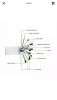
ah right i get you now thank you so much for all the help you give me i will post the results on here when i do the test on my day off from work do i disconnect the hall sensor connector tooYou pull the three bullet conectors apart to disconnect the motor, then put your probes on the yellow and blue, then yellow and green, then blue and green.
hi i will hopefully be doing the test tomorrow to test for the dead short do i disconnect the hall sensor from the controller as well as the phase wires thanks in advance for the answerah right i get you now thank you so much for all the help you give me i will post the results on here when i do the test on my day off from work do i disconnect the hall sensor connector too
It makes no difference. The halls are on a completely separate circuit.hi i will hopefully be doing the test tomorrow to test for the dead short do i disconnect the hall sensor from the controller as well as the phase wires thanks in advance for the answer
Thank you for all the help you give me and many more peopleIt makes no difference. The halls are on a completely separate circuit.
hi i tried to do the test and put it on 200k ohms like you said vfr400 but it kept jumping between 1 and whatever it was trying to do so could tell what all the measurements were supposed to be when i put the probes on have you any idea why or is it that my metre was being a bit dicky lolThank you for all the help you give me and many more people
i did get a reading on the black wire and the red ones stayed the same at 1 so sounds like that is ok as soon as i connect the 9pin motor connector to the the nine pin female connector extension cable that goes to the controller thats when it blows the power so sounds as if its the motor to me but obviously im not too sure trying to find a cheap wheel to try it the motor is a 8fun bafang motor 36v 250w or just another 20inch wheelYou should be able to get three good ohm readings in the 7-14k zone on the GND/Black wire test, it is only the V+/Red with no power that the reading may be 1 and rising. If you get a zero then a fet has gone.
hi any one able to answer this quickly will be a fantastic help ive just done a phase test on the controller and this is what i got b-b 8.9k ohms b-y 4.1ohms b-g 9.88k ohms onthe red side it was r-b 10ohms r-y 8.9k ohms and r-g 18.8k ohmsi did get a reading on the black wire and the red ones stayed the same at 1 so sounds like that is ok as soon as i connect the 9pin motor connector to the the nine pin female connector extension cable that goes to the controller thats when it blows the power so sounds as if its the motor to me but obviously im not too sure trying to find a cheap wheel to try it the motor is a 8fun bafang motor 36v 250w or just another 20inch wheel
P
hi any one able to answer this quickly will be a fantastic help ive just done a phase test on the controller and this is what i got b-b 8.9k ohms b-y 4.1ohms b-g 9.88k ohms onthe red side it was r-b 10ohms r-y 8.9k ohms and r-g 18.8k ohms
[/QUOTE
Please can anyone help me
Thanks pal will order a new controllerThe Yellow wire mosfet is faulty at 4k ohms.
Thanks pal will order a new controller
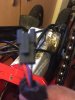
Hi just got round to fitting a new controller and brakes pedal assist still won’t work so peeled a bit of covering away and noticed the red and blue wire are wired differently is this the reason why it won’t workThe Yellow wire mosfet is faulty at 4k ohms.
Attachments
-
 635.9 KB Views: 15
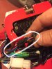
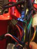
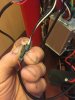
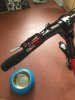
This is the new controller model as I could find the other one also these pics show the the pedal assist connections the one with the cover peeled back a bit is from the pedal assist sensor and the other is from the controller also sorry for being a pain but the brakes I got were red and blue wires i had to put connectors on them and the wires from the controller were black and white so have I connected these up right too your help is always very much appreciatedI looked at your pics on page 1 of this thread and see it is a lishui brand, what did you replace the controller with ?
Attachments
-
 872.1 KB Views: 8
 -
 892.1 KB Views: 8
 -
 866.9 KB Views: 8
 -
 1 MB Views: 8
This is the new controller model as I could find the other one also these pics show the the pedal assist connections the one with the cover peeled back a bit is from the pedal assist sensor and the other is from the controller also sorry for being a pain but the brakes I got were red and blue wires i had to put connectors on them and the wires from the controller were black and white so have I connected these up right too your help is always very much appreciatedI looked at your pics on page 1 of this thread and see it is a lishui brand, what did you replace the controller with ?
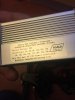
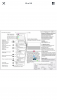
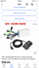
this is the controller I got i only used the controller as the one that goes on the handle bars is more or less the same the last pic is the one i have on the handle bars nowThis is the new controller model as I could find the other one also these pics show the the pedal assist connections the one with the cover peeled back a bit is from the pedal assist sensor and the other is from the controller also sorry for being a pain but the brakes I got were red and blue wires i had to put connectors on them and the wires from the controller were black and white so have I connected these up right too your help is always very much appreciated
Attachments
-
 337.4 KB Views: 6
 -
 369 KB Views: 6
 -
 227.6 KB Views: 6
 -
 830.2 KB Views: 6
Related Articles
-
 MTF Enterprises announces acquisition of EMU Electric Bikes
- Started by: Pedelecs
-
 Wisper 806T folding bike wins Which? ‘Best Buy’
- Started by: Pedelecs
-
 Sustrans calls for protected cycle lanes
- Started by: Pedelecs
-
 Amazon launch their first UK e-cargo micromobility hub
- Started by: Pedelecs
