

Ok I'm having another go at getting the Conhis Controller to work.
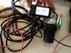
I have connected it all up & its the same as before with nothing happening even though it all seems to be connected right. So I have worked through the Dave checklist taking photo's of the voltmeter at each stage in the hope that someone can spot what's up.
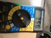
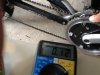
Step 1 - Battery & Power
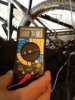
Battery voltage looks fine at 39.1v. I do have 2 fuses (I had the battery all taped up & forgot there was a fuse so added another..) and switch on route to the controller. The reading is taken from the connector after all of this so all looks OK.
Key on throttle is turned on and lights are showing on the throttle & the LCD turns on and shows battery charged.
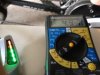
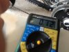
Step 2 - Voltage to Throttle
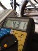
Voltage 4.3v taken across Red & Black Throttle wires - a bit lower than the 5v suggested on the Dave Checklist.
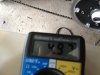
Step 3 - Throttle Signal
Voltage across throttle black & signal wires varies from 0.83v and 3.58v in line with expected range.
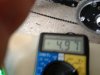
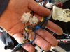
Step 4 - Halls Connector
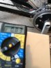
Red & Black shows 4.97v
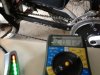
Then testing all the other colours to black & rotating the motor. All show fluctuating voltages as I understand they should.
So there's the puzzle all connected up - all looks fine according to the checklist unless the 4.3v throttle is an issue. But no life to the motor.
Throttle, LCD & ley on/off are all Conhis & came with the kit so connectors just plug in & all looks ok. Other connection appear fine.
I assume the halls & phase wires are not reversed as it works with Dave's old GNG controller with the colours matched.
Any inspiration welcome.
I have connected it all up & its the same as before with nothing happening even though it all seems to be connected right. So I have worked through the Dave checklist taking photo's of the voltmeter at each stage in the hope that someone can spot what's up.
Step 1 - Battery & Power
Battery voltage looks fine at 39.1v. I do have 2 fuses (I had the battery all taped up & forgot there was a fuse so added another..) and switch on route to the controller. The reading is taken from the connector after all of this so all looks OK.
Key on throttle is turned on and lights are showing on the throttle & the LCD turns on and shows battery charged.
Step 2 - Voltage to Throttle
Voltage 4.3v taken across Red & Black Throttle wires - a bit lower than the 5v suggested on the Dave Checklist.
Step 3 - Throttle Signal
Voltage across throttle black & signal wires varies from 0.83v and 3.58v in line with expected range.
Step 4 - Halls Connector
Red & Black shows 4.97v
Then testing all the other colours to black & rotating the motor. All show fluctuating voltages as I understand they should.
So there's the puzzle all connected up - all looks fine according to the checklist unless the 4.3v throttle is an issue. But no life to the motor.
Throttle, LCD & ley on/off are all Conhis & came with the kit so connectors just plug in & all looks ok. Other connection appear fine.
I assume the halls & phase wires are not reversed as it works with Dave's old GNG controller with the colours matched.
Any inspiration welcome.


