

Dave thanks for that, i know it might sound daft but what do i look for..?...a loose wire especially around the key area and internal fuse i guess, otherwise be going out of comfort zone...If yours is the same as this one, there's an instruction of how to open it down the page.
eZee
Reads 40v but just a flicker
- Thread starter geostorm
- Start date
D
Deleted member 4366
Guest
Put a voltmeter on the output connectors, and then wiggle every wire to see if it shows anything on the meter.
Hi Dave disassembled checked fuses and wires all seemed ok reading 40v i think i need to test amperage..Put a voltmeter on the output connectors, and then wiggle every wire to see if it shows anything on the meter.
D
Deleted member 4366
Guest
reassembled , no problem to take apart again, cells appear sealed do i have to remove each pack breaking the wires or......?While you've got it apart, test every cell voltage
D
Deleted member 4366
Guest
If you can't get to the cells, the balance wire will go to a multi-pin connector at the BMS. If it looks like this one, pull it out and there will be little slots on the back where you can measure. Start at one end and measure between 1 &2, 2 &3, 3&4, etc until you have 10 results. Put your probes on the first and the last to get the total as well to measure the total.
It would help of you take a photo of what you have.
It would help of you take a photo of what you have.

Last edited by a moderator:
Within this link you'll see how the battery base slides off, and this link shows the case inside after removing the surround screws, though with older model contents.
N.B. For your purposes ignore the warning not to open the case!
.
Dave thanks the photo at the top of fleccs diagram is the same. only difference i have a blade fuse instead of glass type...
N.B. For your purposes ignore the warning not to open the case!
.
If you can't get to the cells, the balance wire will go to a multi-pin connector at the BMS. If it looks like this one, pull it out and there will be little slots on the back where you can measure. Start at one end and measure between 1 &2, 2 &3, 3&4, etc until you have 10 results. Put your probes on the first and the last to get the total as well to measure the total.
It would help of you take a photo of what you have.
Dave thanks the photo at the top of fleccs diagram is the same. only difference i have a blade fuse instead of glass type...
D
Deleted member 4366
Guest
Unfortunately, from those photos I can't see what wires go where, so I can''t really help you, but there's 5 wires coming from each pack. you could try following them to their connector (outwards from the cells), then unplug them, stick your black probe on the negative output contact, and then check each of the 10 pins in the two connectors, hopefully, they'll go up in steps of about 4v. If so, write down all 10 values.
THANKS FOR THAT Dave, just got back from long w/e so will try what you say when i can get to it, do i need to remove external fuse first..?Unfortunately, from those photos I can't see what wires go where, so I can''t really help you, but there's 5 wires coming from each pack. you could try following them to their connector (outwards from the cells), then unplug them, stick your black probe on the negative output contact, and then check each of the 10 pins in the two connectors, hopefully, they'll go up in steps of about 4v. If so, write down all 10 values.
D
Deleted member 4366
Guest
No point really because you'll be working inboard of the fuse.THANKS FOR THAT Dave, just got back from long w/e so will try what you say when i can get to it, do i need to remove external fuse first..?
40v but just flicker
i connected number 1 and 12 it read 40v seems ok then connecting 1+2 =0.00 --0.07 2+3 = 3.94 3+4 =0.01 4+5 = 0.01 5+6 = 0.02 6+7 =0.00 7 + 8 =0.00 8+9 = 3.98 9+10 =0.00 10 + 11 = 4.04 11+12 =0.00
doesnt look too promising to me, hope this helps.
Hi Dave, at last i have some sort of result, i opened up and removed small board held on by three screws i take it this was the BMS ,anyway it had 12 solder points i n a nice uniform position.THANKS FOR THAT Dave, just got back from long w/e so will try what you say when i can get to it, do i need to remove external fuse first..?
i connected number 1 and 12 it read 40v seems ok then connecting 1+2 =0.00 --0.07 2+3 = 3.94 3+4 =0.01 4+5 = 0.01 5+6 = 0.02 6+7 =0.00 7 + 8 =0.00 8+9 = 3.98 9+10 =0.00 10 + 11 = 4.04 11+12 =0.00
doesnt look too promising to me, hope this helps.
D
Deleted member 4366
Guest
Don't take any notice of those results. You haven't measured them correctly. We're looking for 10 results that add up to 40v. I need a decent photo of what you have, The previous ones don't show enough.Hi Dave, at last i have some sort of result, i opened up and removed small board held on by three screws i take it this was the BMS ,anyway it had 12 solder points i n a nice uniform position.
i connected number 1 and 12 it read 40v seems ok then connecting 1+2 =0.00 --0.07 2+3 = 3.94 3+4 =0.01 4+5 = 0.01 5+6 = 0.02 6+7 =0.00 7 + 8 =0.00 8+9 = 3.98 9+10 =0.00 10 + 11 = 4.04 11+12 =0.00
doesnt look too promising to me, hope this helps.
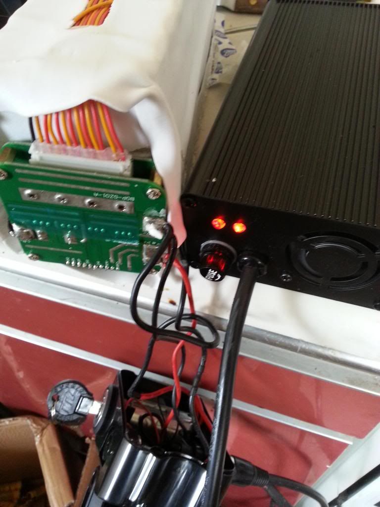
Sorry about readings, did i go to wrong place,? , i enclose photo trusting it shows otherwise on Picassa 1202200531 Dave thanks again.Don't take any notice of those results. You haven't measured them correctly. We're looking for 10 results that add up to 40v. I need a decent photo of what you have, The previous ones don't show enough.
Last edited:
D
Deleted member 4366
Guest
Sorry, I can't find that photo. Can you upload it to Photobucket and post the link here. Instruction in post #3 here:
http://www.pedelecs.co.uk/forum/announcements-feedback-support/15268-does-forum-picture-upload-work.html
http://www.pedelecs.co.uk/forum/announcements-feedback-support/15268-does-forum-picture-upload-work.html
i managed to put on gallery, under Ezee battery interior, the solder spots furthest away is where i got my readings from.Sorry about readings, did i go to wrong place,? , i enclose photo trusting it shows otherwise on Picassa 1202200531 Dave thanks again.
D
Deleted member 4366
Guest
I'm trying to help you, but you're not making it easy. Please do what I said in post #34 with a proper hi res photo, not one that's been cut down, so that I can see what you've got instead of a blurred mess.
geostorm,
if you keep the negative probe on pin 1 and measure the voltage on pins 2, 3, 4, 5 etc up to the last pin (40V) you get the readings more accurately.
Anyway, according to your previous posts, the voltage collapses when the battery is under load, indicating that some cells mayhave been damaged. I suggest you ask d8veh to have a look - it may need some surgery.
C
Cyclezee
Guest
Hi Geo,
I can understand you not wanting to shell out a load of cash on a new battery (did I really say that ), but if I was you, I would snap up D8veh's generous offer and ship the battery to him, if he can't fix it, nobody can
I can understand you not wanting to shell out a load of cash on a new battery (did I really say that
), but if I was you, I would snap up D8veh's generous offer and ship the battery to him, if he can't fix it, nobody can


D
Deleted member 4366
Guest
Unfortunately the photos are too blurred to see what I need. Did you upload to Photobucket the ones you shrank to upload to the forum or the original ones from the camera?
Can you take a photo of the BMS from the other end. Make sure it's not blurred before you upload it.
Compare your photos with this one, which was taken with a cheap mobile phone You can see every detail of every connector. That's what I need:
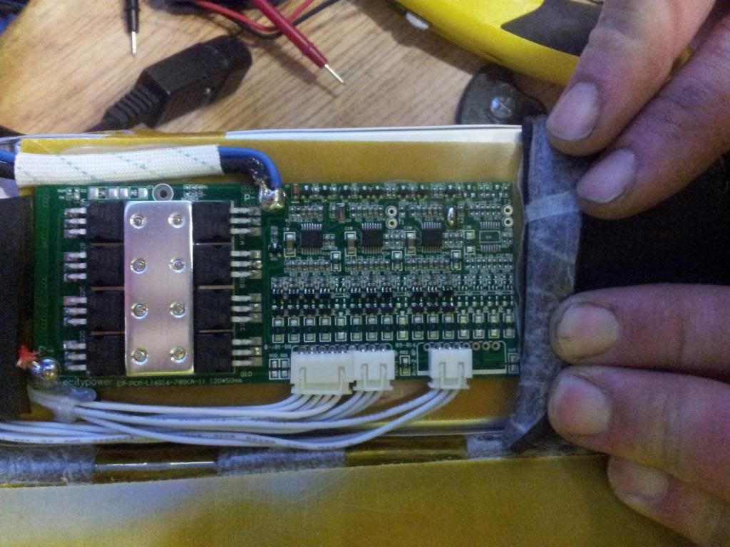
Can you take a photo of the BMS from the other end. Make sure it's not blurred before you upload it.
Compare your photos with this one, which was taken with a cheap mobile phone You can see every detail of every connector. That's what I need:

Related Articles
-
 MTF Enterprises announces acquisition of EMU Electric Bikes
- Started by: Pedelecs
-
 Wisper 806T folding bike wins Which? ‘Best Buy’
- Started by: Pedelecs
-
 Sustrans calls for protected cycle lanes
- Started by: Pedelecs
-
 Amazon launch their first UK e-cargo micromobility hub
- Started by: Pedelecs
