Reads 40v but just a flicker
- Thread starter geostorm
- Start date
D
Deleted member 4366
Guest
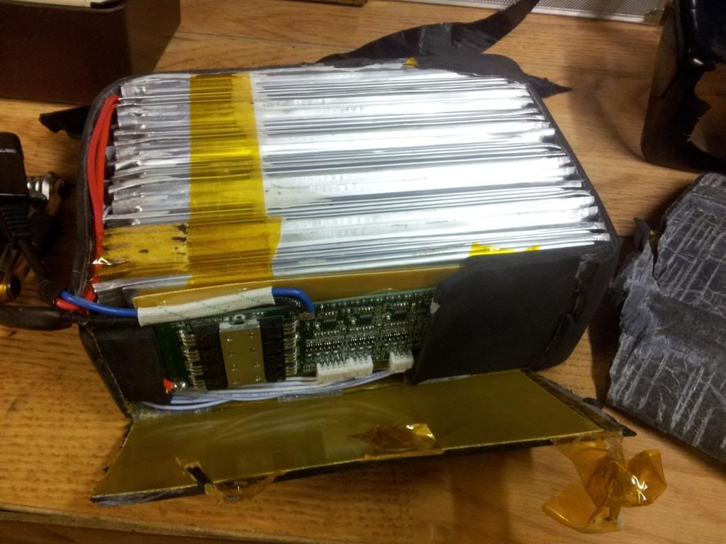
It's this one from BMSBattery. 20aH 36v. Several of us have them, and they work well with 30 amp controllers.8 FETs. Which battery does this neat job come from d8veh?
36V 20Ah Li-Ion Shrink Tube EBike Battery Pack - BMSBATTERY

Last edited:
D
Deleted member 4366
Guest
Unfortunately it doesn't. It's totally blurred like the rest of them.
Dave sorry this is clearer taken different camera
http://i191.photobucket.com/albums/z36/geoffstorm/IMG_0026.jpg?t=1376493527
Last edited:
D
Deleted member 4366
Guest
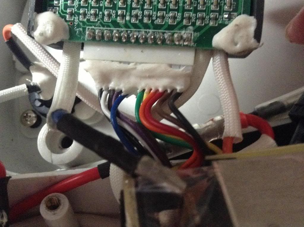
That's better, but I still can't count the wires going in to the connector. Maybe you can do it for me. I can see seven from black to blue. Can you list the colours after that?
C
Cyclezee
Guest
D
Deleted member 4366
Guest
Thanks Dave Johns about right, wires followed by blue are .....purple grey white black or very dark brown. hope this helps .That's better, but I still can't count the wires going in to the connector. Maybe you can do it for me. I can see seven from black to blue. Can you list the colours after that?
Thanks Dave Johns about right, wires followed by blue are .....purple grey white black or very dark brown. hope this helps .That's better, but I still can't count the wires going in to the connector. Maybe you can do it for me. I can see seven from black to blue. Can you list the colours after that?
D
Deleted member 4366
Guest
There's 12 solder pads next to the connector, but 10 wires, correct? So are the two end positions in the connector empty?
There are 11 wires and I cant see any missing, although looking with magnifying glass wider space between blue and green wires. also the blue thick wire on end has pulled out of where its connected to I am not sure, does it fit in where red under battery pack goes thanks, .There's 12 solder pads next to the connector, but 10 wires, correct? So are the two end positions in the connector empty?
http://i191.photobucket.com/albums/z36/geoffstorm/IMG_0027.jpg
Last edited:
D
Deleted member 4366
Guest
I'm getting really frustrated. I counted 6 wires to the blue, in what I could see, and then you gave me another four. 6 +4 = 10, but now you say there's 11. I haven't a clue what's going on, your descriptions are just too vague. I think I have to say that unless you get me a clear photo, I have to give up.
If a blue wire has pulled out, that's probably the cause of all your problems, but I can't tell without seeing it.
I suggest you get someone who knows how to use a camera to take a decent photo that you can upload to photobucket without any resizing, etc. Try your next door neighbour, or their son/daughter who is used to uploading photos.

Sorry about misunderstanding I was under impression you thought there was 11 wires I can empathise with you, my son has taken photo now , hope this is clearer the wire that has pulled is bullet on thick blue in foreground on left not one of the thin wires which go as ......black white grey purple blue green yellow orange red brown black thanks I appreciate the help.
Last edited:
D
Deleted member 4366
Guest
Right, that's much better. It looks like a standard setup: 10 sense wires and a ground.
Pull the connector out. Have a look at the photo below with the connector pulled out. On the part with the wires attached you can see ten slots with metal contacts on one side of it. Hopefully, yours will be the same except eleven or twelve slots.
Get your multimeter and set the dial to 20v DC. Place your black probe the end slot where the black wire next to brown terminates (RHS of photo) and the other on the slot next to it. Write down the voltage. Keep your black probe in the same end slot and measure the voltage at all the other slots in sequence until you get to the end. There will therefore be 10 or 11 results. The last position is empty so the 11th result might be zero. Be sure to check that your probes are making good contact, and give your meter time to settle. Please post the results here.

Right, that's much better. It looks like a standard setup: 10 sense wires and a ground.
Pull the connector out. Have a look at the photo below with the connector pulled out. On the part with the wires attached you can see ten slots with metal contacts on one side of it. Hopefully, yours will be the same except eleven or twelve slots.
Get your multimeter and set the dial to 20v DC. Place your black probe the end slot where the black wire next to brown terminates (RHS of photo) and the other on the slot next to it. Write down the voltage. Keep your black probe in the same end slot and measure the voltage at all the other slots in sequence until you get to the end. There will therefore be 10 or 11 results. The last position is empty so the 11th result might be zero. Be sure to check that your probes are making good contact, and give your meter time to settle. Please post the results here.

Glad that helps about the loose blue wire will I have to connect that first, as not sure where it plugs in.
D
Deleted member 4366
Guest
Right, that's much better. It looks like a standard setup: 10 sense wires and a ground.
Pull the connector out. Have a look at the photo below with the connector pulled out. On the part with the wires attached you can see ten slots with metal contacts on one side of it. Hopefully, yours will be the same except eleven or twelve slots.
Get your multimeter and set the dial to 20v DC. Place your black probe the end slot where the black wire next to brown terminates (RHS of photo) and the other on the slot next to it. Write down the voltage. Keep your black probe in the same end slot and measure the voltage at all the other slots in sequence until you get to the end. There will therefore be 10 or 11 results. The last position is empty so the 11th result might be zero. Be sure to check that your probes are making good contact, and give your meter time to settle. Please post the results here.

The readings are 4.02...8.06...12.11....16.09....1-.....1...,1-...1-.....1-....1.....1....
D
Deleted member 4366
Guest
Its looking good, but you need to move to the next scale to get the readings after 16.09. Once it goes over 20v, the meter displays 1. Do it again with your meter on 200v. Sorry, my mistake.
Related Articles
-
 MTF Enterprises announces acquisition of EMU Electric Bikes
- Started by: Pedelecs
-
 Wisper 806T folding bike wins Which? ‘Best Buy’
- Started by: Pedelecs
-
 Sustrans calls for protected cycle lanes
- Started by: Pedelecs
-
 Amazon launch their first UK e-cargo micromobility hub
- Started by: Pedelecs


