Right I've dived in the deep end this morning and unearthed (what I think) is a horror.
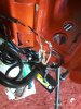
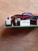
1. First off, something I've been thinking about for a while... the previous owners name is written on the controller. Maybe a sign that it's been in a shop or somewhere to be fiddled with?
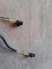
2. A much closer look at the wiring and I noticed some insulating tape which hid the wires for the lights 'twisted' onto the yellow and white wires from the display unit.
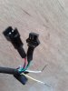
3. So I've taken the bull by the horns and removed the controller and all the wiring from the housing. I had to cut one of the multi plugs off to bet it through the hole.
4. I've ordered a new controller, display and thumb throttle:
Lcd6 Display:
Smarter Shopping, Better Living! Aliexpress.com

s.click.aliexpress.com
Controller:
Smarter Shopping, Better Living! Aliexpress.com
s.click.aliexpress.com
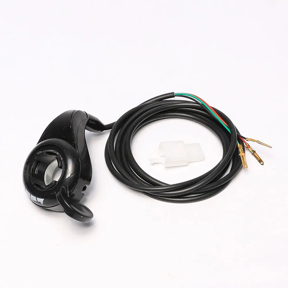
Thumb throttle:
Smarter Shopping, Better Living! Aliexpress.com
s.click.aliexpress.com
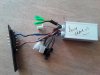
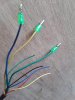
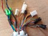
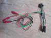
5. I've attached some pics of the wiring I have. Hopefully it'll be a straightforward job of just replacing with new?
The only original components will be the motor and battery. I'm sure the battery is fine, but is there a way that I can check the motor, bearing in mind that i now have nothing connected to it apart from the wiring loom?
Thanks again in advance for taking time to help me. !!!!!!!!.
I wonder if I'll find the same with bike number 2 when I get it here?