

Most motors only have the hall sensors without any other components. Maybe some halls switch better than others and bad ones need other components to clean them up, or maybe some motors don't have such clean magnetic fields as others, so need some sort of cleaning. I don't realy know why they fit those components, all I can do is guess.
Resistors on voilamart front wheel hub
- Thread starter mikeconnect
- Start date
Ok thanks well if you look back at the photo I’ve got 2 resistors on the circuit one of which is faulty so I guess I can’t use ss41. Anyway I need to pass it to somebody cos I’m not able to do these repairsMost motors only have the hall sensors without any other components. Maybe some halls switch better than others and bad ones need other components to clean them up, or maybe some motors don't have such clean magnetic fields as others, so need some sort of cleaning. I don't realy know why they fit those components, all I can do is guess.
Thanks
Ah ok . I’ll post it when I get home . Didn’t think was necessary as the existing photo shows 2 resistorsThe photo isn't complete. You need to show the whole pcb.
The photo isn't complete. You need to show the whole pcb.
Attachments
-
 1.3 MB Views: 12
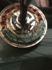
3 blue are sensors . 2 yellow are resistors. Right hand resistor was dead . For some Unknown reason he tried a Capacitor on it . The 3 sensors He put on on are 49E .. Without even checking what originals were or if tHey were faulty In the first place
Attachments
-
 771.7 KB Views: 12
Last edited:
Easiest solution would be for you to get a meter and test the halls.
I can't see the other side of the PCB, but from what I can see, it's like this:
The halls are normal halls connected directly to the 5v supply and ground. Each signal wire is connected directly to the wires attached to the output pads. No other components are involved.
The two things you say are resistors look like capacitors. They're soldered to pads marked for resistors. AFAICS, They're for the speed sensor that's missing from the position marked Q4, who's output would go to the empty pad marked H. They're connected in series between the 5v and the output, so are pull-up resistors. Their job is to hold H at 5v all the time no magnet is over the sensor to switch it, so that it switches back to 5v as soon as the magnet has passed. They would have a value of about 5k each, though the value isn't critical - they could be 50% higher or lower. Without the speed sensor, they have no function and are not needed. To confirm that, you'd need to do some simple meter tests.
Last edited:
Thanks. Please Remember I had an enthusiastic guy who told me he knew what he was doing meddling with this . So here’s the complication .Easiest solution would be for you to get a meter and test the halls.
I can't see the other side of the PCB, but from what I can see, it's like this:
The halls are normal halls connected directly to the 5v supply and ground. Each signal wire is connected directly to the wires attached to the output pads. No other components are involved.
The two things you say are resistors look like capacitors. They're soldered to pads marked for resistors. AFAICS, They're for the speed sensor that's missing from the position marked Q4, who's output would go to the empty pad marked H. They're connected in series between the 5v and the output, so are pull-up resistors. Their job is to hold H at 5v all the time no magnet is over the sensor to switch it, so that it switches back to 5v as soon as the magnet has passed. They would have a value of about 5k each, though the value isn't critical - they could be 50% higher or lower. Without the speed sensor, they have no function and are not needed. To confirm that, you'd need to do some simple meter tests.
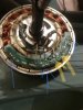
1. the 3 sensors are not the original ones . He fitted type 49e. He guessed this . He didn’t know whatvthe original ones were and worse still he didn’t even know they we’re faulty and again worse he threw them away. So I don’t know what kind of sensors were originally there
2. He did test R1 and R2 and R2 was blown . He again guessed and tried a few resistors but all well below 1k the highest value was 47. Then he fitted a 100nF capacitor on R2 which is still on it . The component on R1 was not replaced and is the original whatever it is.
So in short the 3 sensors are not the originals and probably the wrong type. The capacitor at R2 is not the original and probably incorrect. and I guess If we can Determine what R1 is we can put the same in R2. So I assume there’s no point in testing anything until I replace the 3 sensors And the R2 with the correct type
I found this that might be a direct replacement (2nd from left):

 www.aliexpress.com
You still have the problem that your motor span out and twisted the wires. To blow anything, the wires must be damaged, so it's a waste of time repairing anything if you don't repair the wires. There's no point in discussing anything any further unless you're prepared to test the wires with a meter.
hall sensor on motor with board and cable for lithium electric bike/scooter/skateboard and two wheels havor board and segway - AliExpress 34
Smarter Shopping, Better Living! Aliexpress.com
You still have the problem that your motor span out and twisted the wires. To blow anything, the wires must be damaged, so it's a waste of time repairing anything if you don't repair the wires. There's no point in discussing anything any further unless you're prepared to test the wires with a meter.
Yes you mentioned that in earlier post so Thanks for that . Now the R1 which is the original component how do I tell if it’s a resisitorbor a capacitor49e sensors are for throttles. You need SS41
Measure it with a meter.Yes you mentioned that in earlier post so Thanks for that . Now the R1 which is the original component how do I tell if it’s a resisitorbor a capacitor
Yes you mentioned that in earlier post so Thanks for that . Now the R1 which is the original component how do I tell if it’s a resisitorbor a capacitor
Only just saw this Replacement board Looks like best option but it’s not got R1 and R2. So are you sure ?I found this that might be a direct replacement (2nd from left):
hall sensor on motor with board and cable for lithium electric bike/scooter/skateboard and two wheels havor board and segway - AliExpress 34
Smarter Shopping, Better Living! Aliexpress.com
You still have the problem that your motor span out and twisted the wires. To blow anything, the wires must be damaged, so it's a waste of time repairing anything if you don't repair the wires. There's no point in discussing anything any further unless you're prepared to test the wires with a meter.
I want to emphasise all this stuff is not my thing but I’m sure I could replace the old board with this if it’s correct . Does the board plug in or is it soldered in ?
And I haven’t got a clue how to test wiring But can do with guidance . I’ve got access to a meter but would need an idiots guide on how to test it right down to the basics like do I test with battery off or on etc
Last edited:
Only just saw this Replacement board Looks like best option . I want to emphasise all this stuff is not my thing but I’m sure I could replace the old board with this . Does the board plug in or is it soldered in ?
And I haven’t got a clue how to test wiring But can do with guidance . I’ve got access to a meter but would need an idiots guide on how to test it right down to the basics like do I test with battery off or on etc
ive got the Meter just need guide how to test . Also what about no R1 and R2 on the Ali express boardAs I said, no need to discuss any further until you get a meter.
Set your meter to check continuity (beep). There are three thick pins on the motor connector and 6 thin ones. Each thin one corresponds to one of the solder pads on the pcb: A, B, C, H, 5v and GND. Check that you have continuity from each of those pads to only one pin on the connector out of the 9. If you get continuity on more than one pin or you don't get it on any pin, you need to replace the motor cable, which is very tricky.ive got the Meter just need guide how to test . Also what about no R1 and R2 on the Ali express board
If your meter doesn't have the beep function in the resistance section, set it to the lowest resistance scale, then note what you see on the display when you short the probes. That's what you can expect to see when you have continuity between two positions.
Do that test, then report back.
Will do thanksSet your meter to check continuity (beep). There are three thick pins on the motor connector and 6 thin ones. Each thin one corresponds to one of the solder pads on the pcb: A, B, C, H, 5v and GND. Check that you have continuity from each of those pads to only one pin on the connector out of the 9. If you get continuity on more than one pin or you don't get it on any pin, you need to replace the motor cable, which is very tricky.
If your meter doesn't have the beep function in the resistance section, set it to the lowest resistance scale, then note what you see on the display when you short the probes. That's what you can expect to see when you have continuity between two positions.
Do that test, then report back.
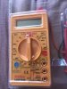
Where’s the motor connectors . Under the PCB? If so how is the PCB removed please ?Will do thanks
Also this multimeter doesn’t seem to beep when I put the two test pens together The display just comes up with different numbers . Sorry it does it’s just quiet . So I just need to know where motor connectors and if below PCB how I remove it
Attachments
-
 1.8 MB Views: 2
Last edited:
Related Articles
-
 MTF Enterprises announces acquisition of EMU Electric Bikes
- Started by: Pedelecs
-
 Wisper 806T folding bike wins Which? ‘Best Buy’
- Started by: Pedelecs
-
 Sustrans calls for protected cycle lanes
- Started by: Pedelecs
-
 Amazon launch their first UK e-cargo micromobility hub
- Started by: Pedelecs
