sw900 display

shore856

Finding my (electric) wheels
Apr 24, 2023
8
0
hello ive just had a quick search and cant seem to see any other thread with this error.

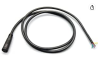
ive got a sw900 display but its a 6 pin waterproof.

my controller is a 5 pin connector.

ive bought an extenstion for the display and ive connected it up with a 5 pin on the end but leaving the white one out ( wired exactly the same way as my other e bike display )
but its coming up with " ERROR 11 "


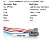
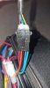
have to mind the bad wiring it looks as its not in the way it is but as its the first time lol please forgive me but this is how it goes as pictured left to right;

red blue black green yellow


the controller colours are throwing me off but here is a diagram of whats what.

everything works it runs and stops but like mentioned its coming up with a communication error and not displaying speed, watts or anything like that.
 

Attachments

shore856

Finding my (electric) wheels
Apr 24, 2023
8
0
i have tried a combination of the green/ yellow cables and ill either get error 10 or 11
 

saneagle

Esteemed Pedelecer
Oct 10, 2010
4,163
2,066
Telford
To make it work, you first need to identify the battery positive wire ( normally red) and the switched battery wire that they often refer to as "lock" (most common is blue then pink or orange). It's very important that those wires are connected to the corresponding one on each side. If you get one wrong, it will almost certainly wipe out your controller, LCD or both. Next, the grounds must be connected. They're always black, so that's easy. With those three wires connected and nothing else, your bike will often work on throttle and maybe PAS1, but you won't be able to use any of the LCDs functions other than probably battery level display.

Here's how it works: The red and black are connected directly to the battery wires, they power the LCD. When you press the power button, the LCD latches on and connects the red wire to the blue, orange or pink wire, which runs back to the controller and powers it. The incoming thick red and black battery wires do not power the controller. they go directly to the motor, but are blocked by the MOSFETS, which are like gates letting power through. The MOSFETS are switched by the controller.

To work, the controller needs power and instructions. It gets both from the LCD . The instructions come via the two comms wires, which can be any colour but mainly green, yellow or white. Without the comms wires connected, the LCD will give an error code, but as it can't tell the controller that because the comms aren't connected, the controller might and often does still work on throttle.

Putting that all together, your photos are nowhere near clear enough, but it looks like you should have red to red, old blue to pink or orange, black to black. For the other two, it's Tx to Rx and Rx to Tx. Your diagram labels them for the new LCD. For the controller side, you need to open the controller to see the markings on the PCB, which will indicate which colour is connected to which. The photo looks like you have the switched power wire to a comms wire, which could be a disaster if it switched on, and it looks like your ground don't match, but in that case it wouldn't work at all so your photo is wrong.

If there's a 6th wire, it's often for the lights or any special function your LCD has.

I don't get you guys, You ask " did I do it right?", then show a birds nest, an out of focus photo or anything else that doesn't show what you've done. With what I've told you, you should be able to sort it out regardless of your photos.
 

shore856

Finding my (electric) wheels
Apr 24, 2023
8
0
hello and thank you for the reply.

so i have 2 e-bikes ive done , and this mentioned display works absolutely fine on my other ebike, displaying everything needed, so i cant have got any wires mixed up so as i mentioned the wires coming out the casing into the connector is not the order it goes, the order was written there, i probably shouldnt have put that picture on as its confusing as it dosent look in order, but just wanted to show the controller wires vs the LCD wire colours, so it goes ;

red to red
blue to orange
black to black
green to blue
yellow to green

so everything matches and works as you've already mentioned but soemthing is still amiss ( and thank you for the extremely efficient accurate description of how the LCD works )


the picture you thought was for LCD is for the controller, the lcd one is for the sw900 and is attached here.


so the other display i had on my other ebike, i have now put it onto this ebike and the display is showing watts now but not MPH still .

i have the 45a version of this but all cables are the same ;

https://cdn.shopifycdn.net/s/files/1/0040/9223/1778/files/36V_48V_52V_35A_3-mode_Controller_Connection_and_User_Manual.pdf?v=1622517260

and this the display im using;


just incase its anything else alltho i cant see it being that reason, i can tell you what other stuff like motor/battery but this problem only risen trying to swap a new controller on.

.
 

Attachments

shore856

Finding my (electric) wheels
Apr 24, 2023
8
0
i think im using a display that isnt compatible with my controller as ive had a issue similar to this before, thank you for the help, your explanation defiantly learnt me something and will help others, many thanks
 

manman94

Pedelecer
Dec 7, 2023
116
2
60
Netherlands
I had the same problem wires all in the correct order for display and kept getting error ,so i decided to change the three main phase wires are around.after doing this i got the right combination all errors disappear.