Theoretical power Vs Actual power

Nealh

Esteemed Pedelecer
Aug 7, 2014
19,991
8,173
60
West Sx RH
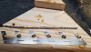
When soldering heavier gauge awg wire, if using a fine or pointy tip it acts like a bottle neck with heat. Although it is very hot it is unable to displace heat efficiently to heat said awg wire and to melt the solder very well so use the chisel flat wider tips to get more heat in place to do the job better and quicker.

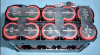
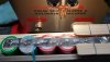
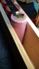
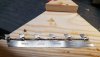
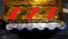
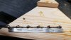
Also if the wire is pre tinned with plenty of solder, starting at the end of the wire puddle the solder on the nickel leaving the iron tip in place and lay/place the wire on to the molten puddle, remove the iron and place straight on top to ensure a good solder joint. The joint should appear molten and very silvery, at this point I remove the iron and use a wooden lolly stick to keep pressure on the joint until the solder changes to a dull cooler colour. Then continues along the wire length, there is no need to have the whole bared wire length soldered down as long as you get four good solder points adj to the cells where the best draw is expected.
 
Last edited:

Blunderbuss

Pedelecer
Mar 11, 2018
158
22
Cambridge
Where i can is use solid copper wire (45amp cooker rated) which i can solder very easily, but the flexible stuff (silicon coated) which i use for connecting to the XTC 60's and last/first group of the cells is more challenging as it is several times fatter (10 AWG) and certainly takes longer to get the heat into (a chisel tip is on its way!) and can be a tight fit on the BMS - maybe i will solder a short length of solid core onto the BMS B and P connectors first, i can then easily connect the 10 AWG flexible to the solid wire.
 

Nealh

Esteemed Pedelecer
Aug 7, 2014
19,991
8,173
60
West Sx RH
10awg should be no problem with 60/80 watt iron with chisel tip use a larger mm size solder as well like 0.8mm or 1.2mm.
1.5mm or 2.5mm stripped twin & earth copper will be plenty for series connection or beefing up, keep any wire length exactly the same. Don't solder series across cell tops/bottoms but across P connector to P connector soldering in between a pair of cells that way you don't directly heat the cell and the nickel connector will dissipate the some heat. Don't leave the iron tip on for more then 2 or 3 seconds, pool a small amount of solder on first then the wire. Weld up a couple of old cells (lf you have any) and have a practice. For series connection the 1.5mm twin and earth copper wire core for battery use should be good for 22/24a.
 

anotherkiwi

Esteemed Pedelecer
Jan 26, 2015
7,845
5,785
The European Union
The table on ES says <19 Amps for 1 mm2 copper wire.

I was thinking of making a jig and soldering the copper wires on before spot welding the Ni strips. Then spot welding a second Ni strip on top for good measure, the parallel connection needs to be able to handle 10 Amps in case of cell failure if I read correctly. Otherwise very low Amp balancing current between cells in the parallel group.
 

Nealh

Esteemed Pedelecer
Aug 7, 2014
19,991
8,173
60
West Sx RH
Quite right AK, for P connection if using nickel just go with two layers of 7.5mm x 0.15mm H strip with the slits in(1.125mm2 or 5a optimal ampacity or 7.44a acceptable ampacity).
If H strip is no good for the pack build cut it in half as single strips the slit is good as it directs the electrode current down for a better stronger weld other wise some of the current jumps between the electrode tips.
For the series don't use nickel just use 1.5mm twin and earth copper core soldered on the P connectors in between a pair of cells for best current share ( ideal if only using a 4p config ) though cells will need a mechanical fixing , welded and soldered connectors shouldn't be relied on for mech fixing. If relying on hot glue or grip fill type adhesive wrap already protected cells in Kapton tape first as any glue/adhesive used won't damage the shrink sleeve and will offer a better surface for application.

With my Arduino Boos spot welder the welds are so much better/stronger using the H strip with slits compared to normal nickel. The stuff I get from Ann on Aliexp is pure nickel.
 
Last edited:

Nealh

Esteemed Pedelecer
Aug 7, 2014
19,991
8,173
60
West Sx RH
The table on ES says <19 Amps for 1 mm2 copper wire.

I was thinking of making a jig and soldering the copper wires on before spot welding the Ni strips. Then spot welding a second Ni strip on top for good measure, the parallel connection needs to be able to handle 10 Amps in case of cell failure if I read correctly. Otherwise very low Amp balancing current between cells in the parallel group.
Weld first P strip on then weld your 2nd strip (which with the copper series added will be a H looking strip), no need then to add a strip on top. Once all finished cover everything with Kapton tape (cheap enough to buy).

Example using a 10a or 15a rated cell for 40/60a rating.
( Pardon me a bit blurry).

The first P strip 7.5mm x 0 .15mm = 5 - 7.44 ampacity.
The series copper wire is 14awg / 2.08mm 2 good for 32a.
The second strip at bottom with series added doubles the side ways P ampacity.
The current hasn't got to travel far, from centre of each cell electrode to series bus is 10mm. Each cell should deliver equal current to the series bus.
This method negates a solder joint at the cell end making spot welding nearly impossible. The v- end of the can should never we spot welded dead centre as this is where the anode is, so offset the P strip on the v- end of the can/cell. The v+ doesn't matter as the cathode is far below and the small contact cap is raised and hollow underneath.
DSCF0913.JPG

If you added extra series bus to the very centre pair or to the two outside cells the cross flow current share would be unequal and some cells will be working harder.
 
Last edited:

Blunderbuss

Pedelecer
Mar 11, 2018
158
22
Cambridge
Quite right AK, for P connection if using nickel just go with two layers of 7.5mm x 0.15mm H strip with the slits in(1.125mm2 or 5a optimal ampacity or 7.44a acceptable ampacity).
.
For the spot welds i do 3 or 4 per each connection (so end with 6 or 8 actual weld spots) when i look at the surface area this encompasses it does not look big enough to take the current - but obviously it is!

Is it as simple as adding a second layer of nickel strip (H strip or regular), doubling up everywhere to double the current carrying capacity. If so does it make any difference where you locate the spot welds for the second layer - so should you do them directly over the cell ends (as per the first layer) or is randomly spreading them out just as good?
 

Nealh

Esteemed Pedelecer
Aug 7, 2014
19,991
8,173
60
West Sx RH
For layering nickel welds don't take very well above previous welds so you need to try and off set the first nickel set to one side of the cell end say to the left on all ends and the second layer to the RHS. The v- end is easy with such a wide base the v+ is a little more challenging but as long as your welds are strong then a pair is all you need, no reason why you cant do the second layer to the side between a pair of cell cans. If you have any old cells have a practice with second weld between the cans, you may get sparking or a bang if the two nickels have a gap between them. Also make sure the v+ cells have an extra insulator placed on them so no damage is done to the v- side part of the can.

If your welds are good and strong a pair of welds per cell should suffice as they shouldn't be used for mechanical holding, cells should be in holders, hot glued or grip filled together.
As I mentioned earlier for gluing cells prep everything, wrap already shrunk cells with a wrap of Kapton so as not to damage the cell can shrink, Kapton is strong and doesn't shrink or tear and has a high heat resistance. Kapton offers a good layer incase of shorting or can shrink damage.
 
Last edited:

anotherkiwi

Esteemed Pedelecer
Jan 26, 2015
7,845
5,785
The European Union
Here is the guts of a DeWalt battery, these are 20700/21700 cells. It would be great if you could buy nickel strip in this format.

Cells21700_11.png
 

Nealh

Esteemed Pedelecer
Aug 7, 2014
19,991
8,173
60
West Sx RH
Mechanical cell holding only needs a two pairs of strong welds.
I expect they are also 0.3mm thick those bus's, for diy welder quite hard to spot but not impossible.
The key though is having the slits so weld current is forced down for a better weld strength. Less heat & current needed to produce goes strong welds.

For welds strength you have to tinker with welder settings, too strong and you get a burn mark to the weld. If you practice with pieces of nickel or old cells try too see how hard it is too pull the weld a part with pliers also look at the penetration depth on the underside, there should be no holes or burning but just a nice dimple.


Jimmy's state of the art welder I believe a mortgage is needed but an do copper.

3S lipo Arduino ones from Aulikira in Korea or the German copy/simial one from malelectrics.eu are very capable and can do 0.1mm copper with 4s though their not really designed to.
They can work with crappy lipos but are so much better with high drain cells like 3s 65/130a graphene or turnigy nano tech.


With crappy lipo I was using 10-14ms setiing to get a quite good weld using a high drain graphene I got better stronger results using 5ms setting and nickel with the slits.
 
Last edited:
  • Informative
Reactions: anotherkiwi

Blunderbuss

Pedelecer
Mar 11, 2018
158
22
Cambridge
I did some tests on some duff cells with a second nickel strip and apart from the occasional arc they went fine (first image), i turned the power down a little and that helped - when i tried to rip it off with some pliers there was plenty of resistance (second image) nothing gave way without fight. Also because it was a quick test i did not clean up the end of the cells as i would normally, so that would give an improvement in quality when i come to do it in anger.

For the soldering i had a go with the H strip, i tinned it and the wire, then soldered them together, then bent the remaining bit of nickel over and soldered again, then spot welded it to the pack.

I put plenty of kapton everywhere and of course the pictures are of the second one i did as the first attempt did not reach the finish post! It was very easy to do and for my soldering looks quite good!

Consider both of the above as adopted practices :D
 

Attachments

  • Like
Reactions: wheeliepete

wheeliepete

Esteemed Pedelecer
Feb 28, 2016
2,047
755
60
Devon
Nice job BB, good to see some battery pack building on here. You and Nealh have given some good tips which I will use on my next build. I've got the same 709 welder as you have, it's had some funny moments, but still woks OK. I just wish the remote leads worked better as they are handy for larger packs. I find they get very hot and tend to burn/melt strip or produce bad welds. They may work better with the slotted strip, which I havn't tried yet.
 
  • Like
Reactions: Blunderbuss

Blunderbuss

Pedelecer
Mar 11, 2018
158
22
Cambridge
Nice job BB, good to see some battery pack building on here. You and Nealh have given some good tips which I will use on my next build. I've got the same 709 welder as you have, it's had some funny moments, but still woks OK. I just wish the remote leads worked better as they are handy for larger packs. I find they get very hot and tend to burn/melt strip or produce bad welds. They may work better with the slotted strip, which I havn't tried yet.
Cheers wheeliepete, i have been trying to soak up everyone's wisdom (Nealh, AK and yourself etc) :)

I did forget to clean the underside of the H strip once i had soldered to it, so i have added that to the "procedure".

I can't get the remote leads to work with any consistency, so gave up pretty early with them, but it does make manhandling the pack a bit of a task when it gets big! I wondered about making some solid arms to extend the electrode holders downwards. I could then put the whole spot welder on a little platform/shelf so the battery pack would slide around underneath. I have seen some reports that the soldering iron is rubbish, but mine works okay, i now use that all the time.

That pack in the picture is going to be used for power tools, it will go in a small messenger bag, that way the drill/grinder etc will be lighter for working overhead and it will have an 18AH battery so keep going for ages.
 

Attachments

wheeliepete

Esteemed Pedelecer
Feb 28, 2016
2,047
755
60
Devon
I've bent the electrodes out to around 45 degrees and can now just about weld 3 cells deep in a pack. I did them in a vice rather than on the welder so as not to damage the clamps.
that way the drill/grinder etc will be lighter for working overhead and it will have an 18AH battery so keep going for ages.
Great idea, wish I'd had been into this a few years ago when building conservatories, could have built a few and sold them to fellow fitters.
 

Nealh

Esteemed Pedelecer
Aug 7, 2014
19,991
8,173
60
West Sx RH
Good job on the discharge wire soldering to the nickel, current will flow along the wire from each cell. With most packs only the very last cell has a discharge wire so more stress on that one cell and is expected to take the whole current to flow.

Also noticeable is the spot welds on the slit nickel look much better then the plain nickel. It is because of the slits there is no side ways flow to the probe ends so the current is direct downwards for a far better weld.
 

Nealh

Esteemed Pedelecer
Aug 7, 2014
19,991
8,173
60
West Sx RH
The two thread links I listed in #16 are well worth a read or three and covers a lot of the basics to constructing better packs for current share, odd number parallel cells are a bit awkward for good power share unless you link every cell in series which means more work and material.
 

Nealh

Esteemed Pedelecer
Aug 7, 2014
19,991
8,173
60
West Sx RH
Bb on your pack this is an option for good current sharing, I have inked in the series connection. Only three are needed instead of six as they are capable of carrying all of the the current, copper wire doesn't have to be used instead 8mm x 0.2 or 10 x 0.2mm copper an be used. Both capable of high good current flow of 20 & 30a respectively.


The cell current will flow the shortest route, the cell either side of the copper bus.
Also on the base of the can watch out for where the welds are placed, don't weld directly in the centre.20181215_143818_LI.jpg
 

Nealh

Esteemed Pedelecer
Aug 7, 2014
19,991
8,173
60
West Sx RH
Nice job BB, good to see some battery pack building on here.
When I start on my Swizzbee packs I will be adding pics to that thread, if my prelim work goes well the build will be a little different to normal parallel & series construction.
 

Blunderbuss

Pedelecer
Mar 11, 2018
158
22
Cambridge
The cell current will flow the shortest route, the cell either side of the copper bus.
Also on the base of the can watch out for where the welds are placed, don't weld directly in the centre.
I was looking at your image in #26 and was thinking about cutting out alternative bits from the nickel H strip, aligning it so that the remaining alternative S connections fall between the cells as you have drawn in #37 and doing two layers of that. From a "production" point if view it would be straight forward to do the first run , turn the power down a notch and do the second layer.