What do controller and motor ratings actually mean

NRG

Esteemed Pedelecer
Oct 6, 2009
2,592
10
The controller / throttle/ motor relationship is voltage controlled not current. The throttle controls the PWM period of the controller which changes the voltage the motor sees and thus its RPM, the current drawn during the PWM period is dependent on motor load and will rise under load up to the controller limit. Maximum load is around 50% of the maximum RPM under no load. The PWM period can remain the same but the motor phase current draw can vary at different loads like when climbing a hill, in this respect the controller is a buck converter trading volts for amps. Torque is related to current but taking it in isolation is rather meaningless, heres a post Tillson made a long time back and explains the relationship better than I can:

A torque figure in isolation is pretty meaningless in terms of giving an indication of power. Power (P) is the product of torque (T) multiplied by the rate at which the the motor or wheel rotates (W). The rate of rotation for this calculation is measured in radians per second and is known as the angular velocity. There are 2 x Pi radians in one revolution, so a motor shaft or wheel rotating at 1 revolution per second will have an angular velocity of 2 x Pi radians per second (Pi = 3.142) so 6.284 radians per second (W)

Taking Power (P) = torque (T) x angular velocity (W)

Therefore, Torque (T)= P/W . If (P), the motor power is fixed at say 250 Watts, by altering W, the output torque is also varied. If W is lowered (reduction gearing, slower bike) torque (T) will increase (better hill climber) And if W is increased by high gearing (fast bike) torque (T) will reduce (poor hill climbing). This is why crank drive bikes are so versatile, you can vary the W part of the equation with the bikes gears.

So, returning to your original point, torque in isolation is not any indication of the power which a motor delivers for the reasons given above.
 
D

Deleted member 4366

Guest
The controller / throttle/ motor relationship is voltage controlled not current.
That's not how I see it. If you look at the attached schematic top right, you will see that all the MOSFETs are attached directly to the 36v supply. The CPU provides the PWM signal, which is amplified to 14v to open the gates to the motor phase wires. Therefore, the only way that power can be adjusted is through timing and pulse width.

http://www.avdweb.nl/Article_files/Solarbike/Motor-controller/China-BLDC-motor-controller-36V-250W.pdf

Also, the throttle doesn't adjust anything directly. The CPU reads its setting and converts that to a desired speed. The CPU knows the motor actual speed from its present pulse timing. It compares that with the desired speed and then uses an algorithm to convert that to a pulse width for power to get to the desired speed. The algorithm is based on both the actual speed and the difference from the desired speed (throttle). When you have a cruise control, you can experience how the algorithm works. Also, the variable PAS levels work on the same basis. The PAS levels are converted to a desired speed, and the same algorithm does the rest.

The above applies to the standard Chinese BLDC controllers. I would think that Panasonic, Bosch, Kalkhoff, etc. use current control rather than speed control because speed control isn't so good for crank-drives.
 

NRG

Esteemed Pedelecer
Oct 6, 2009
2,592
10
Controllers based on the Xeichang CPU are most certainly voltage controlled, JH has written loads about it on ES. The throttle is used to adjust the PWM period, yes the CPU will interpret the voltage and adjust the PWM period accordingly...the apparent voltage the motor sees, RPM is dependent on voltage so the motor is voltage controlled not current controlled. Current draw is dependent on load, the controller is a buck converter it will trade volts for an increase in phase amps. The only time I understand PWM is adjust to lower current is when the controller hits the programmed phase current limit...JH:

Throttle: We need to define what we mean by "throttle". With an internal combustion engine (or an external combustion engine, come to that), the throttle controls the volume of gas in the cylinder. As the torque the ICE produces is directly proportional to this volume, IC engines have a throttle that tends to be a torque control, not an rpm control. It's important to recognise that the controllers we use don't normally work this way, the "throttle" control on an electric motor controller often works as a motor rpm control and doesn't control torque. The throttle on a typical ebike controller changes the mark/space ratio of the pulse width modulated signal to the motor phase wires, in effect it changes the voltage that the motor sees.

...the controller is there to stop things burning out. The only way it can do this is to restrict power and the only way it has to do this gracefully (i.e. without just switching everything off) is to cut back the "throttle", so that the voltage the motor sees reduces. This does increase the motor current if there is a heavy load on it, but by maintaining a safe ratio between battery current (measured by the current limit circuit in the controller) and pulse width applied to the motor the controller is able to restrict motor power to the point where the phase current is relatively safely controlled. It helps to think of the current limiter on one of these controllers as a throttle limiter, because that's what its really doing in an overload condition.

...The controller makes a pre-programmed assumption that the motor time constant is "typical". My guess is that it assumes something like a run-of-the-mill low power hub motor as being "typical". It uses this time constant to guess the likely phase current for any particular combination of battery current, rpm and PWM pulse width. If the PWM pulse width is long (high throttle demand), the RPM is low (low speed) and the battery current is high (high torque demand), the controller will start to reduce the PWM on time to limit the phase current to what it thinks will be the value set in the parameter designer. In practice, the actual phase current will be highly dependent on the resistance and inductance of the motor and wiring, so may well be out by a big factor, possibly double or half the programmed value.
 

trex

Esteemed Pedelecer
May 15, 2011
7,703
2,671
One thing that d8veh said makes sense to me though.
If the throttle setting is converted into current control (between 0-15A for example), that would mimic better a torque sensor.
Is there a controller that works this way or one that one can program oneself?
 
D

Deleted member 4366

Guest
That's still not the way i see it. The CPU is a 5v digital device, so its output can only be a 5v square wave with varying frequency and pulse widths, so how can any voltage be changed in the phase wires? The MOSFEts have a 36v supply directly to the battery. There's no analogue supply to any of the gate transistors, so all they can do is switch on and off. Can you explain from that schematic how any voltage can change? I see 5v, 14v and 36v. Maybe I'm missing something.
 
D

Deleted member 4366

Guest
One thing that d8veh said makes sense to me though.
If the throttle setting is converted into current control (between 0-15A for example), that would mimic better a torque sensor.
Is there a controller that works this way or one that one can program oneself?
I haven't see any current control controllers being sold, but you can get an approximation by using a Cycle Analyst or Speedict that intercepts the throttle signal and has it's own conversion algorithm that makes the throttle behave more like current control.
 

Marctwo

Pedelecer
Dec 1, 2012
182
1
Equal times at 0V and 36V may seem like 18V and can even be measured as 18V by some voltmeters, but it's still just switching between 0V and 36V. That's the whole point of using PWM. If you were actually changing the voltage, you wouldn't need to use PWM aswell.
 
Last edited:

trex

Esteemed Pedelecer
May 15, 2011
7,703
2,671
That's still not the way i see it. The CPU is a 5v digital device, so its output can only be a 5v square wave with varying frequency and pulse widths, so how can any voltage be changed in the phase wires? The MOSFEts have a 36v supply directly to the battery. There's no analogue supply to any of the gate transistors, so all they can do is switch on and off. Can you explain from that schematic how any voltage can change? I see 5v, 14v and 36v. Maybe I'm missing something.
I think both NRG and d8veh are correct, two sides of the same coin.
The current flowing through the motor induces back EMF, as per V = -L delta I / delta T, L being the impedance of the coil. It's worth to remember that these things are not static.
the back EMF is picked up at the phase wires (U, V, W) in the diagram that d8veh attached, attenuated and fed to pins 40, 41 and 42 of the CPU.
 

NRG

Esteemed Pedelecer
Oct 6, 2009
2,592
10
That's still not the way i see it. The CPU is a 5v digital device, so its output can only be a 5v square wave with varying frequency and pulse widths, so how can any voltage be changed in the phase wires? The MOSFEts have a 36v supply directly to the battery. There's no analogue supply to any of the gate transistors, so all they can do is switch on and off. Can you explain from that schematic how any voltage can change? I see 5v, 14v and 36v. Maybe I'm missing something.
The throttle controls the duty cycle of the PWM signal IE: the on off ratio. In each on 'pulse' if you where to look using an oscilloscope you would see many high frequency voltage pulses making up each individual pulse. As each mosfet pair is under the control of the CPU they switch the battery supply to each phase on and off rapidly at the PWM duty cycle. If this where 50% then the voltage each phase will see is 50% of the battery voltage minus any losses. So a 36V supply would appear to be 18V to the motor. The CPU does not drive the phases directly but via switching the mosfet pairs on and off.

Have a google for PWM theory, all should be revealed.
 

Marctwo

Pedelecer
Dec 1, 2012
182
1
But surely the motor never sees 18V (except in the wave slopes), it just acts like it does giving full power for half the cycle and no power for the other half.
 

flecc

Member
Oct 25, 2006
52,793
30,369
I think the motor does see a lower voltage. Similar happens in the lighting circuit of the Panasonic crank unit, the 26 volt battery supply is chopped with a high frequency square wave with roughly 25% "on" duty cycle. As a result the required 6 volts is seen by the loading of the bike's lights, though in truth it's high frequency 26 volts seen on a 'scope.
 

NRG

Esteemed Pedelecer
Oct 6, 2009
2,592
10
But surely the motor never sees 18V (except in the wave slopes), it just acts like it does giving full power for half the cycle and no power for the other half.
No it sees a lower voltage and the motor runs (in this example) at half the speed.


---------------------------------
Posted using Tapatalk :)
 
D

Deleted member 4366

Guest
I still don't think that's right because the timing of the pulses is critical, If you just had an average 18v at half power, there would be no pulses, so the motor won't turn. See what happens when your hall sensors go up the creek, so that the controller can't get its pulse timing right.
 

wurly

Esteemed Pedelecer
Aug 2, 2008
501
9
Yeovil, Somerset
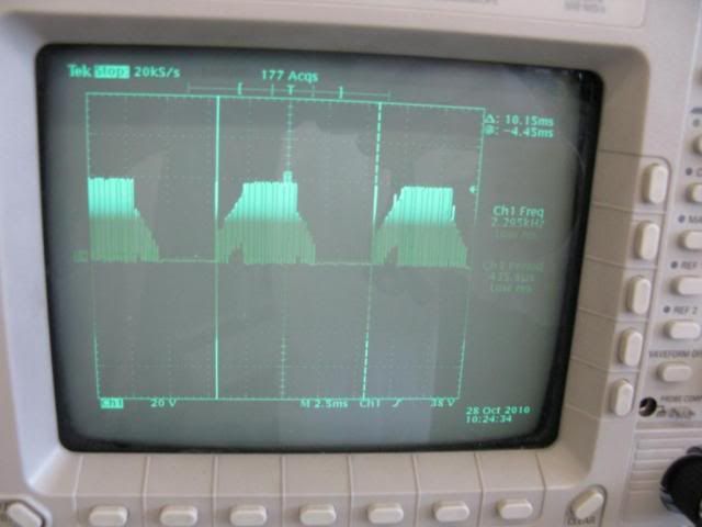
A long time ago i hooked a scope to the phase wires of my old tongxin motor and controller.
This is the result.
Look at the scaling. There is 40V on the motor phase wires. Proof that the motor windings see battery voltage.


Maybe the discussion ought to move towards magnetic flux density, field strength, timing and losses etc?
I love a technical thread, anybody been shown a yellow card yet?
 

Marctwo

Pedelecer
Dec 1, 2012
182
1
I can understand the view that the motor only sees an effective 18V due to it's response time being lower than the frequency of the modulation. But the voltage being applied is still switching between 0V and 36V.
 

flecc

Member
Oct 25, 2006
52,793
30,369
I love a technical thread, anybody been shown a yellow card yet?
No reason for one, it's a technical discussion. Not at all the same as a technical answer given to a non-tech inquirer. Strange how so many tech people can't grasp that simple concept.
 

trex

Esteemed Pedelecer
May 15, 2011
7,703
2,671
I can understand the view that the motor only sees an effective 18V due to it's response time being lower than the frequency of the modulation. But the voltage being applied is still switching between 0V and 36V.
Yes, the voltage at the 3 wire phase wires appear to be 18V but the average current flowing through the motor coil relates to the mark space ratio between the fine pulses. The impedance of the coil varies with the fine pulse frequencies. You can express the relationship between voltage and intensity either ohmically like in V = I x L or use a proper function for electromagnets V = L * N * di /dt.
N is the flux linkage constant of the coil. So although V stays static, i, t and L are not. Note the difference between impedance (changeable) and inductance (constant) of the coil. The motor efficiency can usually be estimated by measuring the phase angle between the I signal and the V signal, something the CPU can do well in Hall-less controllers.
 
Last edited:

NRG

Esteemed Pedelecer
Oct 6, 2009
2,592
10
A long time ago i hooked a scope to the phase wires of my old tongxin motor and controller.
This is the result.
Look at the scaling. There is 40V on the motor phase wires. Proof that the motor windings see battery voltage.


Maybe the discussion ought to move towards magnetic flux density, field strength, timing and losses etc?
I love a technical thread, anybody been shown a yellow card yet?
Thanks Wurly, I was trying to find a 'scope pic showing the PWM signal and that reminded me you posted it on (I think) my Aliem GS thread from a couple of years ago!
 

NRG

Esteemed Pedelecer
Oct 6, 2009
2,592
10
I still don't think that's right because the timing of the pulses is critical, If you just had an average 18v at half power, there would be no pulses, so the motor won't turn. See what happens when your hall sensors go up the creek, so that the controller can't get its pulse timing right.
No sorry Dave that is not right, look up PWM and how it works....this may help:

4QD-TEC: PWM speed control
 

flecc

Member
Oct 25, 2006
52,793
30,369
No sorry Dave that is not right, look up PWM and how it works....this may help:

4QD-TEC: PWM speed control
This extract from those notes:

"In a practical low voltage controller the switch opens and closes at 20kHz (20 thousand times per second). This is far too fast for the poor old motor to even realise it is being switched on and off: it thinks it is being fed from a pure d.c. voltage."

illustrates exactly what I referred to above in the Panasonic unit's similarly switched lighting circuit. The lamp filaments are, like the motor, unable to respond quickly enough to the fast switching so both just see a constant DC lower averaged voltage.
.
 
Last edited: