You have no choice but to ignore the white wire for the time being as your motor doesn’t have a speed sensor fitted there is nothing you can do about it at the moment. You can always fit an external speed sensor if you can’t get the controller to work properly.
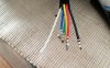
KT controllers have different wiring configurations, depending upon model and supplier. Some come with provision for the white speed sensor wire and some don’t. And there are other wires that may or may not be provided.
Looking at the photos, your controller doesn’t have the wiring coming out for cruise control, lighting, speed control, key lock or regenerative braking either.
You may be able to get away without the white wire because some KT controller configurations don’t rely upon a speed signal from the white wire and instead get speed information elsewhere and that is part of the configuration procedure for the P settings that you will have to do after you get your motor spinning correctly. P2 is an alternative method for calculating speed if your motor has an additional set of speed sensing magnets fitted that the hall sensors can read.
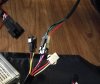
You have two other problems apart from the white wire. Error code 03 is a hall sensor wiring issue that may be a bad connection when you crimped and connected your hall wires from the motor, so check your new wiring first.
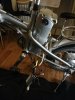
The battery must be supplying power to the KT controller without the key switch needing to be operated otherwise your display wouldn’t work. Although you should try to trace out the key switch wiring to determine how it is connected to your old controller. It may be a key lock for the controller, which is a useful feature because you can power off the controller using the key without removing the battery.
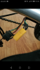
Your cadence sensor goes in to the PAS connector (brown, black and yellow). You can’t do anything about the other speed sensor connector yet (Red, white and black) because you have nothing on the bike to plug into it.

 1.9 MB Views: 33
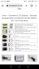 740.9 KB Views: 34