
Just found the invoice - it says 24v 17.5ah battery. Pic attached.
Attachments
-
 40.4 KB Views: 4
I have kt lcd3. I downloaded the manual last night but p1 is unclear as it's asking for information I don't have. I have a testing kit coming tomorrow. I hope it's not hall sensor, but I've doubled checked the wiring :-/P1 and P2 depend upon the gearing of your motor and how many magnets you have for both speed sensing and number of poles. Do you know what make and model motor you have?
Also display manuals are readily available on line and they explain most of the P and C settings, so what model display do you have?
For Error 03, have you double checked your phase sensor wiring? If you have a bad connection in the connector for one of the hall sensors this will show up as a fault. Hopefully you don’t have a bad hall sensor.
Labelling is correct, your bike and battery are 26 volt, 7 x 3.7v cells in series giving 25.9 volts nominal. The mentions of 24 volt are just sticking to the old nominal voltage when we used NiMh batteriesThe battery label states 26v 10ah, but was re-celled to 17.5ah two years ago. I have sent an email to the company to double check for me as there are conflicting specifications online (some say 24v others 26v) so I'm wondering if label is wrong?
Thanks Flecc, could you have a look at the last picture I just added of the invoice as I had it re-celled. They state 24v, so I wonder if it's possible they converted the volts?Labelling is correct, your bike and battery are 26 volt, 7 x 3.7v cells in series giving 25.9 volts nominal. The mentions of 24 volt are just sticking to the old nominal voltage when we used NiMh batteries
But do KT make any 24/26 volt controllers? Only 36 volt upwards as far as I know, so that could be your problem.
.
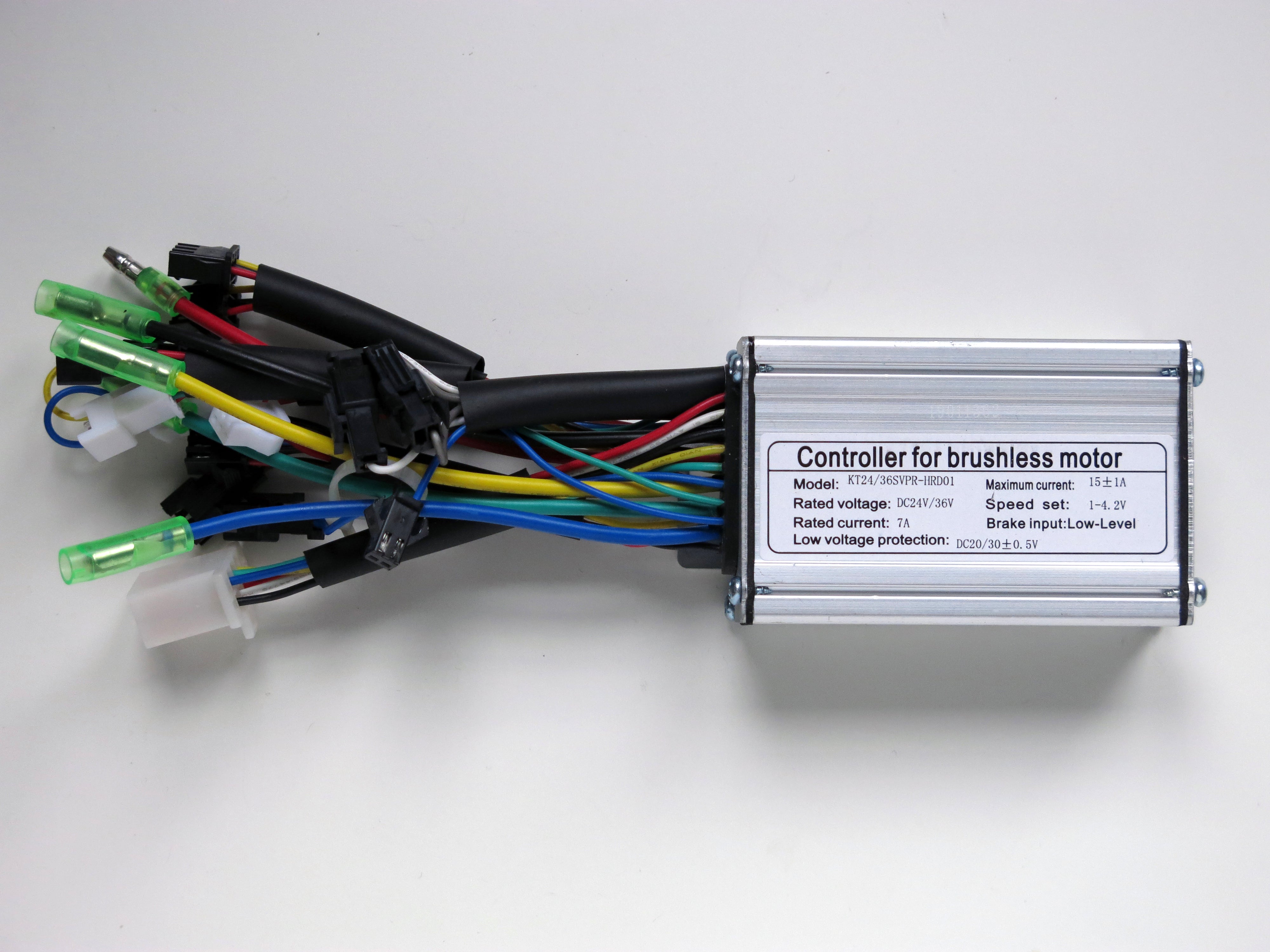
Yes, this is the one I have. The hall sensor colour wires match but could the wiring be different?Yes they do one. This is the controller that I think the op has, coupled with an LCD03 display:
Sensored Brushless Motor Controller DC 24V/36V 250W 6-FET 15A KT Sine
6 fet 15A KT sine wave brushless controller. PLEASE NOTE: This is a sensored brushless motor controller. Your motor should have 8 or 9 wires in order to function with this controller. If your motor only has 3 wires, you will require a sensorless controller. Although this controller can be used...torquetech.co.uk
No, that is just nominal. Many still use the old conventionof saying 24 volts, despite lithium ones being 26 volts now.Thanks Flecc, could you have a look at the last picture I just added of the invoice as I had it re-celled. They state 24v, so I wonder if it's possible they converted the volts?
Yes, I definitely think it's correct - the pas (white, black and red) wire is attached to/enters the magnet thing near the chainring.Also are you 100% sure the the Black/Red & White wire connector is the PAS wiring as I'm sure you have the throttle connected to PAS.
In #16 you show a pic of the PAS sensor Red /Black /Blue connected to controller throttle, Red/Black/Blue or Green for PAS sensor makes sense to me and is a common combo to use as White is often used for speed siganl wire or throttle.
The Red/Black/Bue PAS should connect to controller Brown/Black/Yellow respectively.
Though as I have mentioned Motor Hall sensors need confirming first as intact and switching.
My controller is 24/36/48v Nealh. Ok, I've just tested the hall sensors (just probing/idle) and readings are as follows:I assumed you had 36/48v controller but #1 shows the description in the pic as 24/36v controller.
Not really sure why it isn't working but the 03 error suggests to me that you do have a motor Hall or wire fault, so we need to fault find and start from the beginning.
Start from scratch and just connect the PAS , motor and display forget the throttle for now.
Use a meter and check the motor Hall sensors via the controller Hall connector with battery power on, probe the thin Yellow Hall wire and the thin Black Hall wire. One should see 4.5 - 5v, If you see voltage slowly turn the motor ACW by hand and one should see the voltage switching .
Also do the same with the thin Blue and thin Green Hall wire, one should see the same 4.5 - 5v and the voatge switching as for the Yellow Hall.
If one tests the Hall and doesn't see approx. 5v then the Hall is faulty, like wise if one doesn't see the Hall switch when turning ACW it is faulty. If you turn the wheel to fast then you will see 2.5v .
If one doesn't start with the basics to confirm Halls are intact then one won't get any where.
Ok, I'll do this in the morning as lighting is low now. I'll report back then. Thanks AGS.You have to turn the wheel slowly in an anti-clockwise direction as Nealth said, otherwise the hall sensors won’t turn on and off. It is important to do it anti-clockwise and not clockwise because if you have a geared motor the test won’t work because the clutch won’t engage.
When you turn the wheel anti-clockwise, the magnetic field will trigger each hall sensor in turn, so black and blue will go to 0v and one of the other two will switch to +5v.
They will all cycle in turn. These signals all feed into the controller and are processed together with other signals from your PAS and throttle, then the controller knows when to switch the FETs for each phase on and off that supply the power to turn your motor.
So put the meter back on black and blue, turn the wheel slowly anti-clockwise and it should switch from 4.94v to 0v. Keep turning the wheel slowly and it should switch back to 4.94v. Keep turning the wheel until you see it switch several times and repeat the process on the other two phases.
If they all keep switching between 0v and 4.94v then the test has been successful and your hall sensors are all working properly.
Here is the testing procedure that we have described with some photographs to help you:
The controllers don't cover triple voltage as they dual voltage models, either 24v/36v or 36v/48v.My controller is 24/36/48v Nealh.
Ah ok, maybe 24/36 then - thanks for clarifying.The controllers don't cover triple voltage as they dual voltage models, either 24v/36v or 36v/48v.


