Help! Shengyi DGW07 MISSING C2 CAPACITOR

nepasmecrire

Finding my (electric) wheels
Feb 26, 2024
21
1
Hi everybody
I have a Shengyi dgw07-20j motor on my shitty MOMA ebike.
I had an error 03 "hall sensors" on my KT LCD5 display
Motor works very very badly, slowly and vibrates like hell .
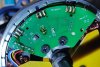
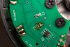
After disassembling it, I noticed that one of the two capacitors was gone from pcb (bad welding?)
I must replace C2, but I don't know its value.
Does someone have an idea?
Is it the same as C1?

Thanks in advance for help.

Pcb picture with the two capacitors (not my picture)

I contacted shengyi , no answer .
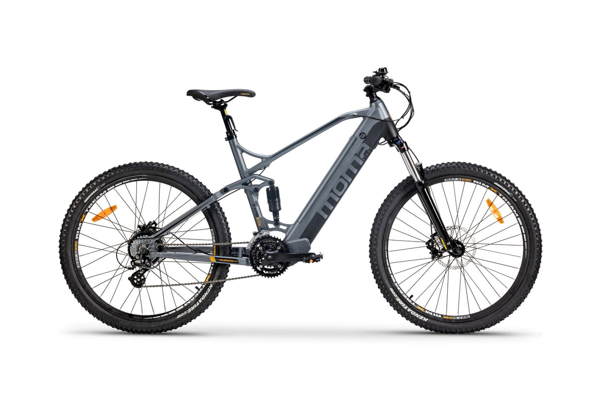

Don't buy this bike , it's a pure **** ! I changed everything on it , except the motor .
I Changed brakes , controller , rear shock absorber , display ,all cables , and it worked a lot better for some months.
 

saneagle

Esteemed Pedelecer
Oct 10, 2010
4,192
2,078
Telford
I doubt that the missing capacitor is the reason for your problem. All they do is remove a bit of noise from the signal. Often, they don't even install them. Are you sure there was ever one there? Can you show a photo of the PCB?

The two most probable reasons for your problem are damage to the motor cable and the motor connector not inserted ALL THE WAY TO THE MARKED LINE.
 

Nealh

Esteemed Pedelecer
Aug 7, 2014
20,134
8,230
60
West Sx RH
C2 is phase sequence, default is 0 and most motors should run correctly with value 0.
Sometimes if the motor sequence is different one can try another value but if the bike runs very noisily, then one should stop immidiatley.

As has been said if you have 03 error then you have a poor connection on the Hall wiring so check the controller Hall connections and the motor cable connector near the motor, the connector MUST be pushed home fully.
Check the cable entry into the axle for wear /damage /splits.
 

saneagle

Esteemed Pedelecer
Oct 10, 2010
4,192
2,078
Telford
Sorry, I didn't see that photo when I looked last time. C1 is for the motor hall sensors. C2 is for the speed sensor (probably not required) and has nothing to do with motor function. The cause of your problem is elsewhere.
 

nepasmecrire

Finding my (electric) wheels
Feb 26, 2024
21
1
The wires are new , connectors are pushed home fully.
No problems with the wires.

The problem occurred on a steep hill, I wasn't on the bike, I was pushing it while holding the trigger. The ground was impassable with rocks, a shock can be unsoldered the capacity. The motor still works, but it is very very slow to start. It vibrates and spins like a 4-cylinder engine running on 3. As soon as I stop pedaling, the assistance turns off. I need to turn the battery off and on again. The C3 error does not appear when the battery is turned on, it is displayed as soon as I pedal.
The motor seems to accelerate 75% and brake 25% at the same time (dificult to explain ) It is clear that it is a problem with synchronisation of hall sensors .
Solder a fresh new capacitor can't hurt the motor . I must know which one a had to solder .
The motor wihout electricity spins free , no problems with internal wires or gears.
 

saneagle

Esteemed Pedelecer
Oct 10, 2010
4,192
2,078
Telford
The wires are new , connectors are pushed home fully.
No problems with the wires.

The problem occurred on a steep hill, I wasn't on the bike, I was pushing it while holding the trigger. The ground was impassable with rocks, a shock can be unsoldered the capacity. The motor still works, but it is very very slow to start. It vibrates and spins like a 4-cylinder engine running on 3. As soon as I stop pedaling, the assistance turns off. I need to turn the battery off and on again. The C3 error does not appear when the battery is turned on, it is displayed as soon as I pedal.
The motor seems to accelerate 75% and brake 25% at the same time (dificult to explain ) It is clear that it is a problem with synchronisation of hall sensors .
Solder a fresh new capacitor can't hurt the motor . I must know which one a had to solder .
The motor wihout electricity spins free , no problems with internal wires or gears.
What do you mean by "fully home". It either reaches the line or not. which is it?

The C2 capacitor has nothing to do with the operation of the motor, and it can't affect it in any way.

The error code you get and the fault that you're experiencing can have a number of causes. 90% of the time, it's a fault with connection at either end of the motor cable or it's cable damage. You can test for that with a meter. Connect everything and switch on. Rotate the motor backwards so that the rotar turns relative to the stator. Put your probes between the black wire and the red wire to check that it has 5v, then check between the black and each of the three hall wires on the PCB. It should show switching on and off with 5v as each magnet passes the hall. Repeat that at the other end of the motor cable or where those wires are soldered to the controller PCB. That test will elliminate all connection issues.

If you don't get 5v between the red and black wire or if it's intermittent, you probably have a short somewhere else, e.g. water in the throttle, damaged pedal sensor cable or anything like that.

You can also get that motor problem when you have a faulty MOSFET in the controller. search this forum how to do a MOSFET test.
 

AGS

Esteemed Pedelecer
Feb 12, 2023
466
141
C2 looks like it is on the under side of the circuit board. And as Saneagle said, it is for cleaning up the speed signal hall sensor. C1 does the same job for the three motor hall sensors. You can easily do a hall test now that you have opened up the motor.
 

Nealh

Esteemed Pedelecer
Aug 7, 2014
20,134
8,230
60
West Sx RH
I thought the op was talking Parameter settings !!!
I too didn't see the pic or link.
 

saneagle

Esteemed Pedelecer
Oct 10, 2010
4,192
2,078
Telford
One other thing. If you look at the left two solder joints of the middle hall, there seems to be something between them. Just in case it's a whisker of solder, scrape it off.
 

nepasmecrire

Finding my (electric) wheels
Feb 26, 2024
21
1
HI
There is no capicity under the PCB. From all the pictures of this motor that I have seen, there are C1 and C2 welded with capacitors.
Here are the tests I did:
I plugged the motor directly into the controller (without the extension cords). It doesn't change anything.
I measured on the pcb +5 and the ground. I have 4.26V.
I tested the hall sensors , on my image this upwards, numbering them from left to right from 1 to 9. I have approximately 4.26V on all wires solders except the 1st, 6th, and 7th where I have 0V
It is very tricky to do , so i am not sure if it is exactely when magnet passes a hall .
 

thelarkbox

Esteemed Pedelecer
Aug 23, 2023
695
219
oxon
You could use the hall sensor solderpads for testing,? with the wheel static at least one will be grounded on the sensor pin to help identify the pinout.

Is it just me or does that C2 position look like something blew in place there?? if so wont that point to something else at the root?
 

AGS

Esteemed Pedelecer
Feb 12, 2023
466
141
I don’t think you have done the hall test properly. You need to slowly turn the rotor around the stator and see if the voltage switches between 4.2v and 0v on 3, 4 and 9. The halls should switch when a magnet passes by. Some halls are bipolar so they will stay switched until they see an opposite magnetic field. Make sure the cable is plugged in properly. The halls need a pull up resistor to operate and these are inside the controller.

Also you need to stop worrying about C2, It doesn’t affect the operation of the motor. I have removed the speed hall sensor on one of my motors and replaced it with a temperature sensor.
 
Last edited:

nepasmecrire

Finding my (electric) wheels
Feb 26, 2024
21
1
Hi everyone, I did the tests again, and yes the voltage varies from 0 to 4.26V when I slowly turn the rotor for each hall sensors. But this time, thanks to my new +3 diopter pair of glasses,and my fingernail between the welds, I discovered that the C2 has not disappeared, the tiny capacity is still there, but it is burned !!!!!!!!! I'm going back to my first request, can someone tell me what the value of C2 is? So I can change it, and see if it works better. Thanks in advance .
 

AGS

Esteemed Pedelecer
Feb 12, 2023
466
141
Have you tested the speed hall sensor with a magnet to see if it still works?

If it’s decoupling capacitor has blown then the hall sensor may also be damaged.

Many motors don’t even come with decoupling capacitors on the hall board.

Also C2 is probably the same value as C1, because it does the same job. So there may be an ID on C1 that can give you a clue to its value.
 

AGS

Esteemed Pedelecer
Feb 12, 2023
466
141
I think I know why your motor is running badly. Looking closely at this photo, the windings look cooked.

See just below the pcb where the wires come out. Some of the windings are black with what looks like blobs of solder on top.

If the insulation has turned black, then it no longer insulates and you have shorted turns in the windings.

If you can remove the pcb and take another photo of the windings we can see what condition it’s in. But it doesn’t look good from what I can see in the photo above.

The reason I removed my speed sensor and fitted a temperature sensor is because I didn’t want to cook my motor.
 
Last edited:

nepasmecrire

Finding my (electric) wheels
Feb 26, 2024
21
1
I don't think windings are cooked , and i can't remove the pcb ( halls are welded , no space to move pcb) but i will make better pictures with a dslr and macro lens.
There is nothing on C1 to indicate his value , nothing !
 

Woosh

Trade Member
May 19, 2012
19,529
16,466
Southend on Sea
wooshbikes.co.uk
Even if C2 was shorted and vaporised, that does not require immediate attention.
Proceed as follows:
1. Test for short circuits. Make sure that a,b,c (Hall signals), and d (speedometer) are not shorted to either ground or 5V.
2. Connect the motor cable but leave the motor case open so you can check various voltages. Switch on the kit.
3. Check that you have 4.5V across ground and 5V
4. Watch the voltage between ground and A while turning the motor core slowly by hand to see the Hall A going from 0V to 4V then back to zero. Do same with B and C. You will know if those sensors are working.
5. Use a fridge magnet to trigger the speedometer sensor. Do same test on D.
 

Nealh

Esteemed Pedelecer
Aug 7, 2014
20,134
8,230
60
West Sx RH
Those phase a carrying wires by the Hall inputs do look very much burnt, burnt wires will mean a great reduction in ability to carry current and drive the motor wheel.