
Help! Shengyi DGW07 MISSING C2 CAPACITOR
- Thread starter nepasmecrire
- Start date
I will retry it , it seemed to work before , but what is D ? (S?) Where is this speedometer sensor ? How i do that with fridge magnet ?Even if C2 was shorted and vaporised, that does not require immediate attention.
Proceed as follows:
1. Test for short circuits. Make sure that a,b,c (Hall signals), and d (speedometer) are not shorted to either ground or 5V.
2. Connect the motor cable but leave the motor case open so you can check various voltages. Switch on the kit.
3. Check that you have 4.5V across ground and 5V
4. Watch the voltage between ground and A while turning the motor core slowly by hand to see the Hall A going from 0V to 4V then back to zero. Do same with B and C. You will know if those sensors are working.
5. Use a fridge magnet to trigger the speedometer sensor. Do same test on D.
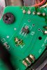
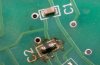
We already know that c2 is just a smoothing capacitor, between pin ground and 5V. You can verify that with your multimeter. The chip it is connected to is the speedometer hall sensor, not much connected to your problem. As I said before, it could have a short and burnt. No need to replace it. Just do what I suggested and find the culprit in a few minutes. It's a very simple diagnosis.
A b c d gnd and 5v are in your post #30. The speed sensor is S1 in #30. Google honeywell hall sensor in SOT-89 and read the technical specs if you want to know how the circuitry works. To test S1, move the magnet over it slowly. The voltage at point D will change when the magnet is in range.I will retry it , it seemed to work before , but what is D ? (S?) Where is this speedometer sensor ? How i do that with fridge magnet ?
Last edited:
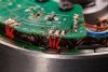
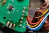
The solder joints on that pcb have been reworked since it left the factory because all of the flux would have been cleaned off during manufacturing.
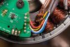
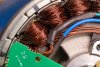
I can see several potential issues from the photos apart from C2, which still looks in one piece. But it may have been overheated when it was resoldered.
1. Part of the phase wiring looks burned.
2. Potential solder bridge on one of the hall sensors, due to way too much solder on the joints.
3. One of the phase wires has been rubbing on the casing exposing part of the inner core.
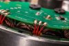
4. Solder splatter on the phase windings.
I can see several potential issues from the photos apart from C2, which still looks in one piece. But it may have been overheated when it was resoldered.
1. Part of the phase wiring looks burned.
2. Potential solder bridge on one of the hall sensors, due to way too much solder on the joints.
3. One of the phase wires has been rubbing on the casing exposing part of the inner core.
4. Solder splatter on the phase windings.
i am sorry , but i don't understand where is "D" , i only see a ,b ,c ,s ,ground ,and +5
d is on the transistor ?
d is on the transistor ?
Forget about C2. It doesn't do anything. I told you before that even if it fell off, you wouldn't see any difference.
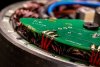
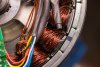
I've never seen the windings in such a mess in any motor. Yours is absolutely terrible. None of the soldering is insulated and they've splashed solder everywhere. You need to check that there are no shorts in the windings.
1. Short to case test. First check the continuity of each phase wire to the case with your meter set to beep. There should be no beep, but check first that the meter beeps when you touch the probes together. If your meter doesn't have the beep function, use any resistance scale to see zero or infinite resistance.
2. Short to winding test/generation test. Set your meter to measure low voltage and put your probes on any pair of phase wires. Spin the motor backwards so that the rotor spins. You should see a few volts generated. The amount of volts depend on how fast you can spin it. Repeat for all three combinations of 2 phase wires.
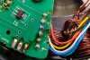
2. Potential solder bridge on one of the hall sensors, due to way too much solder on the joints.The solder joints on that pcb have been reworked since it left the factory because all of the flux would have been cleaned off during manufacturing.
I can see several potential issues from the photos apart from C2, which still looks in one piece. But it may have been overheated when it was resoldered.
1. Part of the phase wiring looks burned.
2. Potential solder bridge on one of the hall sensors, due to way too much solder on the joints.
3. One of the phase wires has been rubbing on the casing exposing part of the inner core.
4. Solder splatter on the phase windings.
On this video , we can see pcb can be removed , so i will try to do it and look under .
3. One of the phase wires has been rubbing on the casing exposing part of the inner core.
(where do you see that?)
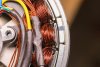
agreed, but it may not have left the factory like that though.I've never seen the windings in such a mess in any motor.
It looks like someone has tried to repair it and didn't do a very good soldering job so he could have cut the sleevings, strings and pulled/creased the wires.
He should at least clean the burn marks.
Last edited:
Related Articles
-
 MTF Enterprises announces acquisition of EMU Electric Bikes
- Started by: Pedelecs
-
 Wisper 806T folding bike wins Which? ‘Best Buy’
- Started by: Pedelecs
-
 Sustrans calls for protected cycle lanes
- Started by: Pedelecs
-
 Amazon launch their first UK e-cargo micromobility hub
- Started by: Pedelecs
