Bafang BBS01 Troubleshooting guide

Nothing2SeeHere

Pedelecer
Aug 14, 2014
32
4
44
I don't suppose someone might be able to post a link to any trouble shooting guides that might have been produced (forum thread etc) for the BBS01 mid drive motor.

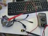
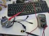
I've had a couple of trouble free years out of my motor. Rode it fine last week. Took the battery off to charge overnight and now the motor won't turn. No error codes on the display and the speed readout was showing a speed when the bike was moving. Disconnected the brake sensors in case the sensor had moved a little far out of alignment. Still nothing.

I haven't noticed any unusual noises to suggest gears have stripped inside and using the thumb throttle I can't hear any motor noise. Pedals still turn so the crank itself isn't jammed (usual high level of resistance as when battery is turned off).

I'm kind of looking for the ' unplug all of these components and plug them back in until it stops working again' type of hints as I'm running out of ideas and I'm not sure how much more I might be able to unplug. Its probably something simple but in my rush to get to work I couldn't think what.

Thank you for any suggestions.
 

Woosh

Trade Member
May 19, 2012
19,406
16,387
Southend on Sea
wooshbikes.co.uk
you will need to test the controller.
 
D

Deleted member 4366

Guest
Take the controller off. It's the little pod-shaped thing on the bottom right of the motor that's held on with three screws. There's some connectors inside. Check them all carefully.
 

Nothing2SeeHere

Pedelecer
Aug 14, 2014
32
4
44
Okay. I shall start disassembling the motor tonight.

I pretty much got to the same position as this guy:


Who seems convinced his controller is dead. He didn't go into any details about how he made that decision beyond he swapped bits over.
 
D

Deleted member 4366

Guest
It's not a big job. One screwdriver, three screws, three minutes.
 

Fordulike

Esteemed Pedelecer
Feb 26, 2010
3,802
1,537
Just the ticket. I was wondering if I would need to remove the whole hub in order to disassemble.

Thanks
Nope, chainring off, loosen or totally remove final drive plastic cover.

Note: you do not have to totally remove chainring or cover, just slide them down the crank arm out of the way.

Then, three hex headed screws as d8veh says. Be careful, the first time you remove the controller screws they are very tight, so use a quality hex key so not to strip the heads.

After that, removal is much easier.
 

Nothing2SeeHere

Pedelecer
Aug 14, 2014
32
4
44
Then, three hex headed screws as d8veh says. Be careful, the first time you remove the controller screws they are very tight, so use a quality hex key so not to strip the heads.
.
Wouldn't you know it, I read this three times and selected my most expensive hex set (didn't have a small enough socket in my socket set). First nut loosed fine. Second fine. Third nut, <snap> the hex key shears level with the bolt head.

Doh!

Looks like I have some engineering to do before I can finish checking. However, whilst my bike was on the stand I did notice that my cable drip loop didn't look long enough since I had adjusted the non driveside fitting. I think there is a reasonable chance under zealous maintenance has encouraged water ingress.
 

Nothing2SeeHere

Pedelecer
Aug 14, 2014
32
4
44
So the controller is removed and I have ordered a replacement controller. I couldn't really see any evidence that it was faulty but there was some evidence of external stuff getting through (some mud coloured dust on the inside)

Assuming the new controller fixes things, is there anyone who reconditions these old controllers that I can send it off too? Its a chunky piece of metal to end up in land fill. I'd rather pass it on to someone who fancied a tinker if possible.
 
D

Deleted member 4366

Guest
It's all potted in silicone rubber, so almost impossible to repair. Don't throw it away. It might not be faulty.
 
usually on the bbs the PAS or the mosfet go brocken and this is very easy to meassure with a multimeter, please check the pic´s. But on the end @d8veh is right it has no sense for repair cause it is very troublesome to clear the silicone for replacing the mosfet it is just a meassurement for to make sure the failure is the controller.
 

Attachments

Nothing2SeeHere

Pedelecer
Aug 14, 2014
32
4
44
usually on the bbs the PAS or the mosfet go brocken and this is very easy to meassure with a multimeter, please check the pic´s. But on the end @d8veh is right it has no sense for repair cause it is very troublesome to clear the silicone for replacing the mosfet it is just a meassurement for to make sure the failure is the controller.
Thanks. I have to admit though that I'm not entirely certain what you are measuring on your multimeter. The connections on my kit are subtly different.

I have received my new controller but I'm still not seeing signs of life. Whats the minimum I need connected to get the motor to turn over when activating the throttle? Display? Wheel sensor? I assume no brake sensors should be fine?
 
D

Deleted member 4366

Guest
To test the motor, you just need the display, the throttle, the phase wires and the hall wires connected; however, that won't work if your throttle is faulty, so you might want to test with the PAS instead. Only connect one of them at a time when testing, i.e. throttle or PAS, not both.

While you have either the throttle or PAS connected (2 tests) and the controller powered up but not attached to the motor, measure between the black and the red pins on the hall connector to make sure that you have 5v there. A short in your harness somewhere could short out that 5v so that the throttle and PAS won't work. If you don't get 5v there, something is wrong somewhere outside the controller.

Another test you can do is to get a 5S connector

http://www.ebay.co.uk/itm/Lipo-Balance-Lead-for-repairing-battery-pack-5s-JST-XH-male-5-cell-18-5V-22AWG-/231134462204?hash=item35d0b000fc:g:8lkAAOSw~OVWty4q

and plug it into the motor hall connector. Apply 5v to the red and black wire positions (ignore the colours on the ebay connector), then measure between the black position and each of the three other positions while you turn the crank very slowly backwards. You should see the 5v go on and off on each of those three wires. Note that although there are 6 positions on the hall connector, only 5 are connected, so you need to measure the corresponding pins. I'm working on one at the moment that stopped for no reason, and all three hall sensors were non-functional, so I'm replacing them.