Brake sensor constantly on

Chris Maluszynski

Pedelecer
Jan 26, 2015
196
1
49
Turn the bike off disconnect both brakes and switch in does every thing work ?
Kit should work with no brakes connected.
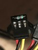
Double check motor wire connector is correctly aligned and connected.

No. Even with the brakes disconnected the display shows the brake symbol and bike won't run. My understanding is the brakes close the circuit and break it when applied? If so the brake symbol should be showing when the brakes are disconnected? Or did I get that wrong?

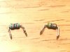
Could the motor wire (the five hall wires) have something to do with this? (that connection is glued on right now, so it could potentially be something wrong), but I thought these wires had nothing to do with the brakes? If there is a chance it is that, I will rip it apart.

Thanks for all the help
 

vfr400

Esteemed Pedelecer
Jun 12, 2011
9,822
3,986
Basildon
My understanding is the brakes close the circuit and break it when applied? If so the brake symbol should be showing when the brakes are disconnected? Or did I get that wrong?
When you pull the brake, it closes the switch, so the symbol comes on and the power goes off.

Let me explain it again. There is an input to the micro-prosessor. It can be 0v (low) or 5v (high. That's all the MP looks for and bases its decisions on. That input is connected directly to the same 5v as the throttle and other sensors, but there is a high value resistor between it and the 5V so it will show 5v, but if you try and draw any current, it will go to zero, which can happen when you measure it with a meter - even a digital one. When you operate the brake switch, it's shorted to ground, so it goes immediately to 0V.

You can check the 5v on the throttle, hall sensors or PAS red wires. They're all connected directly to the 5V regulator, so no chance of meter errors, though you will sometimes see it as low as 4.7v. If it's very low, like 3.7v, there's a short on the 5V somewhere.

The symbol on the LCD comes when the controller sends a data command to the LCD to show it. It's highly unlikely that that can happen by mistake, through not impossible.
 

Chris Maluszynski

Pedelecer
Jan 26, 2015
196
1
49
Oh, ok, I think I'm closer to understanding how the brake signals work then. Sorry for being such a noob.
But. As you say, when brake levers are disconnected all should be working then. I should be able to push throttle for example and get the motor to run?
I cannot do that. Even with brake levers disconnected from the controller, when powering on, then brake light comes on and nothing will run.
I measured voltage on the PAS sensor connector and it was 4.97, so that seems like it's all good.
Not really sure what I should do now. Complain to PSW Power and try to get a replacement controller? Or is there any more troubleshooting left to do here?
 

Chris Maluszynski

Pedelecer
Jan 26, 2015
196
1
49
Ok, here's another one for the idiot scoreboard. I've been measuring voltage between signal and ground (as brake levers do not connect to the red wire). But the 5V is on the red wire not the yellow. Voltage red to black is 4.30V. Not sure if this makes any difference in the problem, but still.
 

Nealh

Esteemed Pedelecer
Aug 7, 2014
20,112
8,219
60
West Sx RH
I expect if you use a 3 wire hall sensor brake all will be well, though KT do state when using 2 wire brakes to omit the Red 5v line.

With my KT's I only use 3 wire hall sensors and dismantle the wired sensor block and lob the levers.
 

Chris Maluszynski

Pedelecer
Jan 26, 2015
196
1
49
I expect if you use a 3 wire hall sensor brake all will be well, though KT do state when using 2 wire brakes to omit the Red 5v line.

With my KT's I only use 3 wire hall sensors and dismantle the wired sensor block and lob the levers.
Nealh, you lost me there. Sorry. I'm completely new to this.
Could you explain what all this means to my case?

"I expect if you use a 3 wire hall sensor brake all will be well,"
This is not what I have is it? My brake levers have two wires?

" though KT do state when using 2 wire brakes to omit the Red 5v line"
Exactly. My brakes levers are not connected to the red, only black and yellow.
(But it seems not to be working...)

"With my KT's I only use 3 wire hall sensors and dismantle the wired sensor block and lob the levers."

I don't think I understand any of this. Does it contain a key to what I should be doing now?
What are 3 wire hall sensors? (Should I get different brake levers that have 3 wires?)
Which wired sensor block?
What does "lob the levers" mean?

Again, sorry for being such an amateur.
 

vfr400

Esteemed Pedelecer
Jun 12, 2011
9,822
3,986
Basildon
There are brake switches like yours that are mechanical and require two wires, and there are ones that work electronically, which need a 5v supply direct from the 5v regulator. Both of them short the signal to ground to cut the motor power.

The three wires are:
Red - direct 5v
Black - common ground
Yellow - signal wire 5v through a high value resistor

To get the brake symbol, your brake input signal has been pulled to ground. That can be by a fault on the pcb, like too much bare wire where it's soldered, but could be a solder blob or anything like that, but whatever it is should be obvious; or a short in the wiring or connector.

If your meter has a continuity beep function, you could try testing between the yellow and black wires. A beep will confirm the short. If there's no beep, it must be a software fault. That test should give a definitive answer for what to do next.
 

Nealh

Esteemed Pedelecer
Aug 7, 2014
20,112
8,219
60
West Sx RH
Quite simply I have always used 3 wire hall sensor brakes with my KT's.
Have never used or tried the two wire set up so don't know if it works or not.
All my disc brakes are hydraulic so the actual levers are of no use, so I dismantle the lever and lob/throw them in the scrap pile. This leaves me with just the wired sensor to fit to my brakes and I use a simple piece of right angled aluminium to act as a stop end for the sensors plunger/switch.
Inside the lever the wired sensor terminates in to a small nylon/plastic enclosure on the end is a small sprung plunger that acts as a switch to move a tiny magnet away or to the sensor when I activate my hydraulic levers.

Won't be able to do it today but see if I can take a pic or two and post them tomorrow.
 

vfr400

Esteemed Pedelecer
Jun 12, 2011
9,822
3,986
Basildon
I have a potential solution. This might work as long as there is no direct short of the signal wire. Take a resistor somewhere in the range 5k to 10k and poke one end into the connector's the 5v pin and the other in the signal wire's one. Do it to each connector in turn to see if the brake symbol disappears.

If you're not familiar with resistor codes. any resistor with a black first band and orange third would be OK or Brown black and orange for a 10K one. If you have anything that's electronic and broken, you can probably find one in it.

Resistor codes:
 

Chris Maluszynski

Pedelecer
Jan 26, 2015
196
1
49
Still haven't been able to find a resistor, will keep looking tomorrow. But in case this works: What would be a permanent fix? Would the resistor have to be soldered somewhere? I'm guesing the current scenario repeats on each power up.
 

Nealh

Esteemed Pedelecer
Aug 7, 2014
20,112
8,219
60
West Sx RH
Inside the levers is a switch contact or sensor wired like this, the plastic housing end in the brake lever uses a sprung plunger.
DSCF1005.JPG

The two wired switch is just that it relies on a continuation (a short) contact to be activated (like a latching switch) and when dormant/off requires the plunger to be in (no short ). No magnet is used inside but simply relies on a simple switch assembly inside that relies on two minute springs and minute little metal bar for a an on/off contact.

The other type uses a three wire Hall sensor (magnetic sensor) looks much the same but inside the end housing utilises a different set up and simply relies on a spring and magnet to be used to make or break the contact as it passes the sensor.

I did tell a fib my Boardman does use a two wire switch with a KT controller, except my KT controller uses a dedicated two wire connector to the pcb ( utilising only Gnd Black and Yellow Signal) and not the Hall type one.
 

Chris Maluszynski

Pedelecer
Jan 26, 2015
196
1
49
Agh. Can't find the right resistor. Found a charger that had 1k (brown black red gold) and a 20k (red black orange gold) resistors, suppose that's out of range? I will try to go to a store tomorrow and buy one if I don't find any other junk at home.

Nealh, thanks for the explanation about the 3-wire sensors.
 

Chris Maluszynski

Pedelecer
Jan 26, 2015
196
1
49
After three days of looking for places to buy resistors locally, I took to the desperate measure and went to the city dump today and took off with a pile of electronics junk that I've been tearing through all night. Finally I found two little buggers that I identfied as 10k and 4.7k. Tried both, but unfortunately all this work for nothing. The damn break light i still on.

What to do next?

31449IMG_4969.jpg31448
 

Chris Maluszynski

Pedelecer
Jan 26, 2015
196
1
49
Also, I double checked voltage on all the connectors with the 5V red wire. They are all 4.37V. It was suggested above that this can be as low as 4.7 and would suggest a short if it was 3.7V. So what do I make of 4.37? Could it be a short? And if so, would that be the problem? Should it be possible to locate the short?
 

Nealh

Esteemed Pedelecer
Aug 7, 2014
20,112
8,219
60
West Sx RH
These things are relatively inexpensive, unless you are a pcb/electronics wizz then repairing is beyond most of us so replacement is likely best.
You can try opening a dispute though I don't think the PSWPower direct route gets good results, that why when I buy KT stuff or any thing from vendors I use Aliexpress and there process often favours the buyer.
 

Nealh

Esteemed Pedelecer
Aug 7, 2014
20,112
8,219
60
West Sx RH
Do you happen to know if there are aby prticular sellers on AliExpress that have ”fast” shipping (ie not 10 weeks)?
I have used Okfeet before about 2 weeks door to door.
Also have used C & D.
Both were 14 days.

For a controller try and find one with dedicated two wire brake connector if using two wire brake cut out to rule out conflict issues.

This one I can't remember how long it took but was certainly with in 3 - 4 weeks.
Although 25a an lcd3 allows current reduction by at least 5a, some newer firmware versions allow 50% current reduction.

 
Last edited:

Nealh

Esteemed Pedelecer
Aug 7, 2014
20,112
8,219
60
West Sx RH
KT stuff isn't all the same, they supply a lot of customer custom made stuff with differing configurations. Some custom stuff will have different M/F Julets and some come with or with out light output, also current ratings and as you have seen brake wires configuration.
The 9 mosfet models run cooler then the 6 mosfet ones, better/more fets and slightly larger ali case.