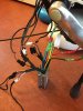
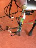
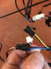
The length doesn't matter because you have to cut it a few inches from the motor end, then turn it round and solder the wires from each part. You can cut a bit off if it's too long. You need this motor extension cable rather than the one with the block connector on one end:if i decide to get the connector to reattach the cables just incase i decide to take the wheel of to work on it away from the bike do you know what size it will be and how to measure it please

Black 9-Pin E-Bike Bicycle Female To Male Connector Motor Extension Cable 3 Size | eBay
Find many great new & used options and get the best deals for Black 9-Pin E-Bike Bicycle Female To Male Connector Motor Extension Cable 3 Size at the best online prices at eBay! Free delivery for many products.
www.ebay.co.uk