hall sensors

Bobbington

Pedelecer
Feb 20, 2019
33
1
I have sent a message to Panda Ebikes but not sure if I will receive a response, so I'll post it on here to see if the knowledgeable people on here can
shine some light on my problem?.......

Hello Panda Ebikes,

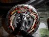
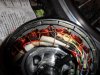
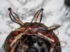
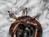
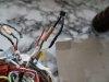
I have the regular 250W hub motor kit. The motor packed in after 200 miles of use, under max power up a long hill.
After stopping for a breather I started to go again, the bike Juddered and stopped with code 03 flashing on display.
The fault code Manual said it was .."Hall Sensor". I have read they can be replaced.
On your technical pages it mentions... "Or change to a NO Hall controller?"
Would this be a straight exchange or would there be additional technical work to be done?
I'm hoping you can help me, currently this kit has cost me £2,50 a mile to run. I'm am reliant on my Ebike to find work.

Very Best Regards,

BH


Eagle

Esteemed Pedelecer
Aug 31, 2012
381
134
Bobbington,

You have probably seen this info on Panda’s website:

What if a hall sensor breaks?
A common issue with hall effect motors is that a hall sensor breaks, due to water damage, overheating, short circuiting, over-voltage, or some other reason.
If this happens, the motor won’t work with a hall effect controller, because the controller will get confused.
In that instance, you need a no hall controller , these controllers use a clever trick of electrical engineering to detect motor position without the need for hall sensors.
But that is the subject for another blog post!

https://www.pandaebikes.com/hall-effect-brushless-motor-controllers-work/
Maybe Panda or somebody on here can recommend a suitable No Hall controller.

Try ringing a Panda dealer:
https://www.pandaebikes.com/dealers/

You could also send a personal message to member danielrlee whose shop is here:
https://www.ebay.co.uk/str/danielrlee1980?_trksid=p2047675.l2563
 
Last edited:

Bobbington

Pedelecer
Feb 20, 2019
33
1
Hello Eagle, Thanks for your very quick response.
Yes.. I did see it on Panda & tried to find a number, but the only contact info I could find was email.
Its been a fast leaning curve for me as I'm trying to get my bike back on the road as soon as possible with as little expence as I can get away with. I will try to find a Panda dealer's number. I have spoken to ebike dealers last week, but they where £2,000 + bike sellers and weren't interested.
I welcome your advise.
Bob.
 

vfr400

Esteemed Pedelecer
Jun 12, 2011
9,822
3,986
Basildon
Hall sensors don't normally blow these days. The problem is more likely a simple connection issue. First, make sure that the connector near the motor is pusshed all the way in, then, if you have bullet connectors at the controller, make sure that they're tight. Many of the bikes I have to fix are because that motor connector was not pushed in all the way to the line.

Unfortunately, if you try and run a motor with a faulty connection, there's a good chance that you blow the MOSFETs in the controller.

To find out what's wrong now, you need a meter to do some measurements. To test the MOSFETs you need to completely disconnect the controller and measure the resistance between red battery wire and each of the three motor phase power wires. The meter should be set to measure kiloOhms. Each result should be the same. You might get a changing reading, so try and record what it starts at. Repeat using the black battery wire. Again, the three readings should be the same. They won't change this time. Any significant difference between the three readings indicates a blown MOSFET.

You can test whether your motor hall sensors are OK as long as you have the white block connector at the controller. Don't waste your time with it unless the above test shows OK. Power up the controller with everything connected. Measure the voltage between the red and black on the white 6-way connector. It should be around 5v. If it isn't, there's no point in continuing. If it is, measure the voltage between the blue and black while you rotate the wheel backwards slowly. You should see the 5v switching on and off. Repeat the measurement between the green and black, then yellow and black. All results should be somewhere around 7K to 14K with the first three often, but not always higher.
 
Last edited:
  • Like
Reactions: Bobbington

Bobbington

Pedelecer
Feb 20, 2019
33
1
Hi vfr400 MC, Thanks for your help.
I have put a friends wheel on my "Bike system" & it ran fine, which suggests everything before the motor is fine. Watched Youtube .. a chap in USA his motor failed, 1 of his hall sensors turning the voltage on & off was down on voltage, changed all 3 it was then OK. these things led me to the sensors, which are on ebay 6 for £5. But there isn't a circuit board in my motor, just wires that run from the connecting plug then laced to the coils, (not easy to test for continuity) not easy to change. I would have to cut the lacing. I have a tester & I have some photo's of the inside motor, I may cut the lace tomorrow and check for damaged wiring, I've got nothing to loose now, I'm sure somebody with your experience in these things could sortit . I'm frustrated how much this kit cost and the mileage I did (200) before it packed up, :confused: £2.50 /mile.
BH.
 

vfr400

Esteemed Pedelecer
Jun 12, 2011
9,822
3,986
Basildon
Hi vfr400 MC, Thanks for your help.
I have put a friends wheel on my "Bike system" & it ran fine, which suggests everything before the motor is fine. Watched Youtube .. a chap in USA his motor failed, 1 of his hall sensors turning the voltage on & off was down on voltage, changed all 3 it was then OK. these things led me to the sensors, which are on ebay 6 for £5. But there isn't a circuit board in my motor, just wires that run from the connecting plug then laced to the coils, (not easy to test for continuity) not easy to change. I would have to cut the lacing. I have a tester & I have some photo's of the inside motor, I may cut the lace tomorrow and check for damaged wiring, I've got nothing to loose now, I'm sure somebody with your experience in these things could sortit . I'm frustrated how much this kit cost and the mileage I did (200) before it packed up, :confused: £2.50 /mile.
BH.
This is the problem. People read stuff on the internet and then jump to conclusions. I don't know how many bikes I've had to fix with symptoms like yours, but I can say that only one had a faulty hall sensor, and that was a big direct drive motor like the one in that video, where hall sensor failure is more common.

The only problems you'd get on your kit that could cause hall sensors to fail are water inside the motor or burnt motor. Water only temporarily stops the hall signal and I've never personally had to fix a burnt motor. Both of those possibilities would be obvious when you opened the motor.

There are still ways to test hall sensors in the motor if you show us photos of what you have.

After you took out the motor, did you test it again to see if it works when you have a proper connection? If not, it might be an idea to try it.

I'm assuming that you have a 250w Panda kit with a geared motor. If it's not that, tell us what you have.
 
Last edited:
  • Like
Reactions: Bobbington

djah

Pedelecer
Apr 24, 2018
74
3
54
Ireland
Hi guys.
Just to add my experience. I had, or should I say, my wife had two motors fail in similar circumstances that you describe. Max power on a long hill and then she used the throttle. Info 3 error on the screen. I got a replacement motor which cured the issue but my curiosity got the better of me. It’s a q128 motor. I bought individual hall sensors on AliExpress and replaced all three internal halls. It wasn’t too difficult, just time consuming, as the sensor are soldered to a small PCB. All worked fine after replacing them.
It sounds like replacing them in your type of motor could be more difficult.
As it happened in two different motors, it leads me to believe they are not capable of prolonged climbing despite what the manufacturers claim.
 
  • Like
Reactions: Bobbington

Bobbington

Pedelecer
Feb 20, 2019
33
1
Hi guy's, djah, vrf400, Eagle,
EAGLE your vid post isn't the one I sore. Mine is a 250W motor. The Video I saw was a 250w hall sensor replacement.
Its not a Panda kit, which I presume is better quality than mine. This kit came from EBC in Devon ( now closed down) Cost £435 with Batt, I've seen a very similar kit on ebay (without Batt) for £116. Cheap kit, Cheap motor!
I did think about purchasing the kit, But couldn't justify the cost for just the motor wheel.
I did test the wheel after the strip down , it had the same problem.
My only course of action now, having read your helpful posts is the "simplest & cheapest" to attempt to change the Hall sensors.
My experience with my 1st ebike has not been great. I'm put off spending much if any money ( I haven't got much) on this type of transport . I need to get this bike fixed as cheap as poss. Hall sensor change appears to be the cheapest, if not the easiest (for me).
I appreciate all your help with suggestions and comments please continue. It brings me back to the 1st post, Will a No Hall controller? be a straight swap and fix the problem if it is the Hall sensors causing the problem?
SAM_2187.JPGSAM_2189.JPG


Last edited:

vfr400

Esteemed Pedelecer
Jun 12, 2011
9,822
3,986
Basildon
Which connector do you have on the motor? If it's the 9 pin round one, do youhave the extension that runs to the controller and does that end have a 9 pin or the white 6 pin block?

General rule. Never repair anything until you've tested that it's faulty.
 

vfr400

Esteemed Pedelecer
Jun 12, 2011
9,822
3,986
Basildon
The easiest way to test is to remove the pins from the block on the end of the extension so that you can apply 5v to the black and red wires. You can use an old USB charger, any 5v charger or three AA cells joined together. Once you have that sorted, you only have to measure between the blue and black with a voltmeter while you turn the motor backwards. If your hall is working, you'll see it switching the 5v on and off. Repeat for the other two colours (not white).

To get the pins out of the conne tor, you need a watchmakers screwdriver or similar to hold the barb down through the front while you pull the pin out the back. You can do everything with the pins still in the block, but it's very awkward. Maybe just remove the red and the black.
 

Bobbington

Pedelecer
Feb 20, 2019
33
1
SAM_2192.JPGSAM_2193.JPG
The easiest way to test is to remove the pins from the block on the end of the extension so that you can apply 5v to the black and red wires. You can use an old USB charger, any 5v charger or three AA cells joined together. Once you have that sorted, you only have to measure between the blue and black with a voltmeter while you turn the motor backwards. If your hall is working, you'll see it switching the 5v on and off. Repeat for the other two colours (not white).

To get the pins out of the conne tor, you need a watchmakers screwdriver or similar to hold the barb down through the front while you pull the pin out the back. You can do everything with the pins still in the block, but it's very awkward. Maybe just remove the red and the black.
Hello VFR
 

vfr400

Esteemed Pedelecer
Jun 12, 2011
9,822
3,986
Basildon
You can't test them like that. You can only test at the end of the cable, though at least now you don't need to turn the wheel. They should switch when you bring a magnet to them, but it needs to be oriented the right way.

While you have them out, see if you can read the number on them.
 

Bobbington

Pedelecer
Feb 20, 2019
33
1
Hello VFR, Ref your Q pins & blocks, I made a mistake with info about wires in the White block. Had trouble trying to read the numbers on them , they are embossed not printed.Th best I could do is 3144? & 2nd line underneath 818? but they where worn so not sure.
 
Last edited:

Bobbington

Pedelecer
Feb 20, 2019
33
1
There are 6 wires in the Block, 9 in the cable extension. Had trouble trying to read the numbers on them , they are embossed not printed.Th best I could do is 3144? & 2nd line underneath 818? but they where worn so not sure.......

Tried to get a 5v to the circuit, but struggled, needed another pair of hands.
 

vfr400

Esteemed Pedelecer
Jun 12, 2011
9,822
3,986
Basildon
Sorry, I forgot that you already tested them. Here they are. Let us know how you get on.
https://www.ebay.co.uk/itm/5-Pcs-3144-Hall-Effect-Sensor-Magnetic-Detector-4-5-24V-VHss/123622489543?_trkparms=aid=555018&algo=PL.SIM&ao=2&asc=20160908110712&meid=facddef638f74081830c7f27ffa15ab5&pid=100677&rk=3&rkt=30&sd=273308875020&itm=123622489543&_trksid=p2385738.c100677.m4598

I think you should replace the ones you have, but I'm not 100% sure we have got to the bottom of this. Yours aren't burnt, they're not corroded and they're not on the 5v rail, so all the normal reasons for failure don't apply. Can you describe the circumstance of how your motor packed up?
 
Last edited:

Bobbington

Pedelecer
Feb 20, 2019
33
1
Hello VFR, Your indications for not failed are true, but the 5v point was not confirmed, I didn't get to complete the check thoroughly.
Motor Failure......
A long moorland road, 2 mile-ish, Max power (5), stopped a couple of times on the climb up, after stopping Third time, set off for last 50 mtr, on 2nd pedal bike juddered stopped, screen started flashing code 03 (bike manual says.. 03= Hall sensor).
I powered down restarted battery, set off down the hill, motor ran for 2 seconds then failed again 03. On the way home, on a slight gradient powered up started to pedal motor ran but screen flashing code 03 & motor making a loud "rumble noise" sounded like an industrial 3 phase motor with a phase down, then failed after 100 mtr.
My thoughts now while the motor is split to cut off the sensors strip the wire back to give access to the Tester and check for continuity from the white block extension plug, if OK, change the 3 sensors. If all Fails then its going in the bin & selling for parts.
 

Bobbington

Pedelecer
Feb 20, 2019
33
1
Hi VFR, Just found a problem, The sensor wires that run from the motor plug to the sensors, 1 is detached from 1 wire that comes out of the sensor. It was hidden inside the heat sleeve that sits on one of the motor coils. if the motor had a circuit board it probably would not have happened or would have been easier to spot.
I still need to replace the sensor because the sensor wire has come out of the sensor. Consequently there isn't anything to reconnect the signal wire too.SAM_2196.JPG
 
Last edited: