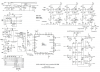
It's very simple. The battery wires are connected directly to each motor phase in both directions. The only thing stopping current from flowing is the 6 mosfets (one for each direction in each of three phases), which are basically electronic switches. The controller CPU opens the mosfets in short pulses to let current through. The sum of the currents coming out of the controller must be equal to the current going into it, so the average current in each phase wire must be 1/3 of the current in the battery wires. You have inductors and capacitors that can store energy and release it, so within each pulse, all sorts of weird things happen, but you can't create any extra energy.I'm not sure that Mtr Amps (motor winding phase currents) represent the peak currents, perhaps they represent average current in some way.
Here's something that's been puzzling me for a while - if rpm is low so that the controller is current limiting then what actually limits the current? The FETs switch the field coils between the 0v and 36/48V so does the controller turn them off as soon as it detects the current limit through the shunt? What then about the inrush currents?
Your description in term of average energy being applied makes a lot of sense, and is the way I approach things, but I'm struggling to see how the control electronics work when they are current limiting.
The controller controls the current by measuring the battery current through the shunt, then limiting it through each of the 6 mosfets with the PWM duty cycle. When I talk about pulses, there are two types. When you look at how three phase motors work, we talk about timed pulses to kick each phase around to move the magnets from one pole to the next, but each pulse is made up of a subset of much smaller PWM pulses, and now that we have sine-wave controllers, the PWM for each pulse varies throughout the pulse.

Last edited: