How to add a throttle to a Carrera Vengeance E Spec

rajeshtailor

Pedelecer
Jun 5, 2020
170
3
no, it's just one added precautionary step which I borrow from vfr's earlier post #105.
The extra initial step lets you write the code and test it while the bike still fully working.
ah ok makes sense.

we still stick to the original plan.

To recap:

Arduino PinControllerSensorThrottle
GNDblackblackblack
VINred
5Vredred
A1yellow?
A2yellow
A3green
A4yellow
A5green
LED pin 13


Connect only VIN, 5V, GND and throttle signal first (which colour is the signal wire on your throttle?).
Let's make sure that everything still works as it should.
Then write your code to make sure you can see and control the output before connecting the sensor's and controller's yellow and green.
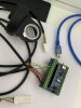
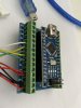
The throttle signal wire is white. I'll aim to give this a shot by the weekend.
 

Woosh

Trade Member
May 19, 2012
19,529
16,466
Southend on Sea
wooshbikes.co.uk
after you can control the frequency of the LED blinks (you want about 0-18 blinks/sec), next step is to write the code to mirror A2-A3 to output the same on A4-A5.
When that's done, you should be able to connect the yellow and green wires to the arduino.
 

rajeshtailor

Pedelecer
Jun 5, 2020
170
3
So I'm trying to test this on my PC locally so I can get some serial output in a debugger. I'm using the original code for now just to test the throttle value however when I change the throttle the values don't change in the debugger they stay at a constant value (see screenshot), is this because there is not enough power to drive the throttle and I need to actually plug into the bike Controller?

40734
 

vfr400

Esteemed Pedelecer
Jun 12, 2011
9,822
3,986
Basildon
What voltage do you measure on the signal wire? it should go from 1.2v to 3.8v when you adjust the throttle. What voltage does 357 relate to?

Personally, I'd use the Arduino only to make a 1khzhz pulsed signal all the time the bike is switched on and send it to the green wire, then connect the throttle directly to the red black and yellow wires.
 

Woosh

Trade Member
May 19, 2012
19,529
16,466
Southend on Sea
wooshbikes.co.uk
show us a picture of your arduino as it is connected to the PC and the throttle at the moment.
Check with a multitester that the voltage at the A1 (throttle signal pin) changes as expected when you push on the throttle.
 

jokskot

Pedelecer
Jul 14, 2018
156
47
75
or... Ditch the Arduino (as I've previously indicated I had no joy with that approach) and try my solution described in post 100 of this thread
 

Woosh

Trade Member
May 19, 2012
19,529
16,466
Southend on Sea
wooshbikes.co.uk
I’ve attached a photo of the setup unfortunately I don’t have a multimeter so will need to source one ASAP
It's very good so far.
Let's just wait until you have got a multimeter.
 

rajeshtailor

Pedelecer
Jun 5, 2020
170
3
or... Ditch the Arduino (as I've previously indicated I had no joy with that approach) and try my solution described in post 100 of this thread
I do like the sound of this however I'm not a electrical engineer :) so need a more step by step guidance, you talk about a switch is that another component that needs to be purchased and wired in? Any other components that need to be wired in? Do you have a photo of the finished solution?
 

rajeshtailor

Pedelecer
Jun 5, 2020
170
3
So tested with a multi meter and first checked the power voltage supply that reading was 4.7v then I checked the throttle reading and at no throttle it was reading 2.80 and at full throttle it was reading 2.79. Something must be wrong with the throttle. Do you suggest I order a new one can anyone recommend any?
 

Woosh

Trade Member
May 19, 2012
19,529
16,466
Southend on Sea
wooshbikes.co.uk
don't but another throttle just yet.
Get a 1 kilo-Ohm resistor and put it across pin A1 (throttle) and ground.
It may fix your problem. If that does not work, put the resistor across pin A1 and VIN.
The resistor creates a proper load for the signal pin.
 

rajeshtailor

Pedelecer
Jun 5, 2020
170
3
don't but another throttle just yet.
Get a 1 kilo-Ohm resistor and put it across pin A1 (throttle) and ground.
It may fix your problem. If that does not work, put the resistor across pin A1 and VIN.
The resistor creates a proper load for the signal pin.
Ok ordered a pack of 100 cheapest I could find! Will try this tomorrow.
 

rajeshtailor

Pedelecer
Jun 5, 2020
170
3
don't but another throttle just yet.
Get a 1 kilo-Ohm resistor and put it across pin A1 (throttle) and ground.
It may fix your problem. If that does not work, put the resistor across pin A1 and VIN.
The resistor creates a proper load for the signal pin.
I tried to test this but its a painful without a breadboard from my initial tests it produced the same results as previously. Does the resistor need to go in a certain direction between the 2 points?
 

rajeshtailor

Pedelecer
Jun 5, 2020
170
3
Just an update. Looks like the throttle issue was down to me using an extender, I removed an extender julet cable and plugged the throttle directly into the Arduino and now it's working (at least in the debug monitor).

I am utilising the original code here and this is my output in the serial monitor.

The value 549 is when the throttle is lowest.
The value 210 is at full throttle.

40816

I also have it outputting blinks via the on board LED all fine.

So I have also modified the code so when I am pedaling I pass the values directly from the PAS Sensor to the Controller via the following lines of code:

Code:
void pedalon()    //Called when pedal is moved
{
  if (throttle == false) { //Only passes signal if throttle is not being used, otherwise ignored.
    if (analogRead(3) == HIGH) { // I'm pedalling according to analog pin 3 the cadence
      digitalWrite(LED_BUILTIN, HIGH); //Light the LED to show we are working
      analogWrite(4, analogRead(3)); //Pass the cadence value coming from PAS straight to controller
      analogWrite(5, analogRead(2)); //Pass the torque value coming from PAS straight to controller
    } else {
      digitalWrite(LED_BUILTIN, LOW);
    }
    Serial.println("pedal round..");
  }
}
What is the general consensus? Shall I move testing to the bike?
 

Woosh

Trade Member
May 19, 2012
19,529
16,466
Southend on Sea
wooshbikes.co.uk
Not yet.
Now write your code so that when the throttle is at a minimum, the LED will blink once every second (1 Hz) and when the throttle is at maximum, 5 times a second (5Hz).
After you've done that, set A4 as analog out, when the throttle is at a minimum, output 0V, when the throttle is at maximum, output 3V.
 

rajeshtailor

Pedelecer
Jun 5, 2020
170
3
Not yet.
Now write your code so that when the throttle is at a minimum, the LED will blink once every second (1 Hz) and when the throttle is at maximum, 5 times a second (5Hz).
After you've done that, set A4 as analog out, when the throttle is at a minimum, output 0V, when the throttle is at maximum, output 3V.
Done. :)

So A4 is the Torque value going to the controller, do I need to do anything with A5?
 

Woosh

Trade Member
May 19, 2012
19,529
16,466
Southend on Sea
wooshbikes.co.uk
check with the multitester that you have the expected voltage on pin A4 when you use the throttle.
Next job, read the pedal sensor (pin A3) and output it on pin A5.
Mirror the output A5 to the blinking LED so you can visually check your code.

You want ultimately to be able to switch between torque sensor mode when the throttle's voltage is less than 20% to throttle mode when the throttle outputs more than 1V.
 

rajeshtailor

Pedelecer
Jun 5, 2020
170
3
check with the multitester that you have the expected voltage on pin A4 when you use the throttle.
Next job, read the pedal sensor (pin A3) and output it on pin A5.
Mirror the output A5 to the blinking LED so you can visually check your code.

You want ultimately to be able to switch between torque sensor mode when the throttle's voltage is less than 20% to throttle mode when the throttle outputs more than 1V.
So something strange going on. I am testing with the multimeter and it is giving me strange results (I think). So when i test the voltage for the throttle I get the following:

When the throttle is at its lowest the throttle reading = 3.82, and the Torque (A4) reading = 4.65
When the throttle is at full throttle the throttle reading = 0.72, and the Torque (A4) reading = 0.00

I thought it should be the other way around like a low reading at low throttle and high reading at high throttle.

Also when going from low throttle to high throttle the torque reading on the multimeter drops rapidly fast!

Any thoughts. I haven't done any testing on the bike yet this is purely code and multimeter testing.
 

Woosh

Trade Member
May 19, 2012
19,529
16,466
Southend on Sea
wooshbikes.co.uk
install a load resistor between the white wire of the throttle and GND.
It should stabilise the voltage reading.
Which pin on the arduino did you connect the throttle signal wire to?
 

Advertisers