

I got so sick after months of messing about trying to modify the carerra to be better uphill, that I bought a 1000w motor kit for the front wheel which works via a throttle, I attached brake sensors to cut the motor as well. Im getting old so cant manage the hills where we live, but now I generally use the back motor on the pedal assist, then bring in the front with the throttle for more assistance. Job done, flying up the hills now!Wrong, throttle is 3 wire, this could be some programming lead or perhaps more likely an output for lights as suntour has that option. This kit works by tricking the pedal sensor signal so it will plug between the two connectors for that I'd imagine. I got tired with the limiter replaced the controller and pas with a common Chinese one with throttle, achievable if you know how to crimp terminals to match, and the bike is heaps of fun now
I think the advice i'm going to give him is that if he wants to stick with a torque hub then install a new kit. At which point I would say he is better off shopping around for a non electric carrera, selling his current bike and use that to pay for it all.I got so sick after months of messing about trying to modify the carerra to be better uphill, that I bought a 1000w motor kit for the front wheel which works via a throttle, I attached brake sensors to cut the motor as well. Im getting old so cant manage the hills where we live, but now I generally use the back motor on the pedal assist, then bring in the front with the throttle for more assistance. Job done, flying up the hills now!
Glad you found a solution that works for you though
")
Its a bit of a faf on with two batteries tho, the new one with the controller is mounted in a back box, if I use the bigger motor sparingly, I get closer to a 60 mile round trip, just a little bit throttle on the small gradients and it takes the load off the back one.I think the advice i'm going to give him is that if he wants to stick with a torque hub then install a new kit. At which point I would say he is better off shopping around for a non electric carrera, selling his current bike and use that to pay for it all.
Glad you found a solution that works for you though
Are you able to share where you purchased the 1000w front wheel kit from? Thanks!Its a bit of a faf on with two batteries tho, the new one with the controller is mounted in a back box, if I use the bigger motor sparingly, I get closer to a 60 mile round trip, just a little bit throttle on the small gradients and it takes the load off the back one.
Hi, I got mine from Ebay, search for 1000w 48v electric bicycle conversion kit hub. its easy to fit on the front wheel at £136.99. The battery is purchased separate mine was USB 48V11.6AH E-bike lithium battery for 100w motor £219.90. Hope that helps, regards richardAre you able to share where you purchased the 1000w front wheel kit from? Thanks!
Persuaded him it wasn't worth it to him, as it genuinely wasn't. His bikes still under warranty and all he wanted was a few more mph on the limit to speed his commute. for ebike kits though I have seen some dual motor controllers about don't know if anyone knows much about them though, previously seen them on dual magic pie bikes.Hi, I got mine from Ebay, search for 1000w 48v electric bicycle conversion kit hub. its easy to fit on the front wheel at £136.99. The battery is purchased separate mine was USB 48V11.6AH E-bike lithium battery for 100w motor £219.90. Hope that helps, regards richard
I'll get my scope on it and see if that's what we get with the CarreasAny help??View attachment 34089
Can I ask, do you by any chance have a pin out for the controller wire I want to do this on my bike ut unsure of that aspectUPDATED v1.1 code (30/05/2018)
Improved the pulse conversion from the throttle
Improved the pulse replication from the pedal
So, with the kind help from Tony at Wooshbikes.co.uk I've been able to complete this little project.
If I were to do it again I would most likely go for a throttle grip rather than a thumb one, as it would be easier to fit. If you are going to use a thumb throttle then you can only fit one of the left side as the right you have the gears and they get in the way.
To complete this little project I used
Arudino Nano v3 (eBay etc.. )
Thumb accelerator (Wooshbikes.co.uk)
Replacement PAS - pedal assist sensor (Wooshbikes.co.uk) only require as my original one was broken
Below is the diagram for wiring it all up.
View attachment 25014
All the above does is generate a pulse which would normally come from the pedals. I've coded it so you can still use the pedals if the throttle isn't being used.
Please test before adding power from your controller... I tested mine in the Arduino serial monitor and it should output as..
No output when nothing is happening.
On low throttle you should see around 550.
On full throttle you should see around 80.
No throttle but moving pedals - see text pedal round..
View attachment 25017
If you see any other values you may need to adjust the range. This is done in the following lines....
pulseoff = (510 - (val / 1.4))+220;
This seems to output a range of 70 - 580.. 580 is when the throttle is off, anything above 560 is ignored. (works in reverse).
Any questions please ask awayCode:// Wrote by CdRsKuLL 30th May 2018 v.1.1 // Updated pedal code to match input when throttle not being used. // Updated range as it was stalling the motor at to fast. // Please have fun but always test the output before connecting it the the bike.. safety first!! // http://diyrc.co.uk http://wooshbikes.co.uk int throttlePin = 0; int pulseoff = 600; int pulseon = 0; int val = 0; bool pulse = false; bool throttle = false; int pedalin = 2; unsigned long startMillis; unsigned long currentMillis; void setup() { pinMode(LED_BUILTIN, OUTPUT); pinMode(pedalin, INPUT); digitalWrite(LED_BUILTIN, LOW); attachInterrupt(digitalPinToInterrupt(pedalin), pedalon, CHANGE); startMillis = millis(); Serial.begin(9600); } void loop() { currentMillis = millis(); val = analogRead(throttlePin); pulseoff = (600 - (val / 1.7)) + 120; pulseon = int(pulseoff / 3); if (pulse == false) { if (pulseoff < 550) { if (throttle == false) { //removes the halfsecond possible delay on first start up. digitalWrite(LED_BUILTIN, HIGH); throttle = true; pulse = true; } else { if (currentMillis > (startMillis + pulseoff)) { //send pulse digitalWrite(LED_BUILTIN, HIGH); Serial.println(pulseoff); pulse = true; startMillis = millis(); throttle = true; } } } else { throttle = false; } } else { if (currentMillis > (startMillis + pulseon)) { pulse = false; digitalWrite(LED_BUILTIN, LOW); } } } void pedalon() //Called when pedal is moved { if (throttle == false) { //Only passes signal if throttle is not being used, otherwise ignored. if (digitalRead(2) == HIGH) { digitalWrite(LED_BUILTIN, HIGH); } else { digitalWrite(LED_BUILTIN, LOW); } Serial.println("pedal round.."); } }
Hope this comes in handy for others.
Video below was before I recieved the throttle from wooshbikes.. just a proof of concept.
View attachment 25018
View attachment 25019
3D printed Arduino Nano temp case
View attachment 25023
View attachment 25025
View attachment 25024
Steve
I followed this project for a while but it's a long time ago, I think the OP has abandoned it.
If you can write your own code and rig up your own arduino kit, then you can identify easily the 4 wires that come out of the ATS sensor board: black: ground, red: 5V, yellow and blue: pedal sensor and torque sensor outputs. I can't remember which one is which but it does not take long to find out. Just turn the cranks, one of the two will pulse, that's the pedal sensor.
If you can write your own code and rig up your own arduino kit, then you can identify easily the 4 wires that come out of the ATS sensor board: black: ground, red: 5V, yellow and blue: pedal sensor and torque sensor outputs. I can't remember which one is which but it does not take long to find out. Just turn the cranks, one of the two will pulse, that's the pedal sensor.
I'm pretty sure that you don't need to do anything complicated like that. Connect a throttle to the red, black and yellow wires in the torque sensor and it should work. All we need is someone to try it to confirm. If you splice the wires so that the torque sensor remains connected, both the torque sensor and throttle should work at the same time. Whichever gives the higher signal takes precedence.Can I ask, do you by any chance have a pin out for the controller wire I want to do this on my bike ut unsure of that aspect
The pinouts are:
red : power supply 5v
black : ground
yellow : torque sensor signal 1.5v - 4.3v
green : pedal rotation signal pulsing 5v
I thought i made a quick post regarding this.
Just before i went on vacation i managed to get it to work on my carrera vengeance e bike as well (the new version)
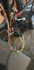
Sorry for the wire spaghetti mess, but i do have it all on video with a throttle working and on a whiteboard showing where it all goes.
Once i return i will post the rest of the pictures and the video.
Just before i went on vacation i managed to get it to work on my carrera vengeance e bike as well (the new version)
Sorry for the wire spaghetti mess, but i do have it all on video with a throttle working and on a whiteboard showing where it all goes.
Once i return i will post the rest of the pictures and the video.
Ok I have returned.
I assembled everything with a 3d printed box and the one thing that i didn't test because of my tight workspace was the pedals. And of course the pedal sensor doesn't function at this point.
My findings is the following:
- The only way that i can make the throttle work without the controller throwing a code 21 or 22 is to combine the green pedal rotation from both the controller and the PAS to D13 on the nano and also combine the torque sensor from the throttle with the torque sensor from the controller to A0.
If any is disconnected then it will throw either code and cease the controller until you reboot it.
- While testing throttle only i noticed that if i keep the throttle on for more than 8 seconds, the controller ceases and throws code 21. Rebooting will fix this and if the throttle is just pressed for a few seconds, let go and repeat then you'll be fine.
So now i need help tricking the system to the controller so it sees the pedal rotation signal. If i do a direct connection it still won't work and throws code 21.
I'm still very new to Arduino and I'm more comfortable with python but is there a way to put in Arduino a false signal to the pedal rotation signal so the controller doesn't cease up?
For reference:
- Code21: Torque sensor electrical problem
- Code22: Torque sensor mechanical problem
I want to give this a try it looks pretty straight forward I’m competent with soldering/wiring/coding however I just don’t know where to source the right cables anyone know where to buy
1) throttle
2) cable to feed the controller
3) cable to accept the pas input cable
1) throttle
2) cable to feed the controller
3) cable to accept the pas input cable
I tried that, but it didn't work. I bet the controller needs the rotation signal before it'll give power, like any non-zero start controller.I'm pretty sure that you don't need to do anything complicated like that. Connect a throttle to the red, black and yellow wires in the torque sensor and it should work. All we need is someone to try it to confirm. If you splice the wires so that the torque sensor remains connected, both the torque sensor and throttle should work at the same time. Whichever gives the higher signal takes precedence.
The pinouts are:
red : power supply 5v
black : ground
yellow : torque sensor signal 1.5v - 4.3v
green : pedal rotation signal pulsing 5v
I spent some time last year trying to get the the device described in the OP to work on a generic bike, but without success . The OP author seems to have gone into hiding and Woosh who were involved in supporting some of the early development were not able to give me any further help or information.I want to give this a try it looks pretty straight forward I’m competent with soldering/wiring/coding however I just don’t know where to source the right cables anyone know where to buy
1) throttle
2) cable to feed the controller
3) cable to accept the pas input cable
I also tried an even simpler approach... mathieupassenaud.fr/electricBike/
but had no joy with his publication either.
I'm not incompetent or unfamiliar with electronics and the Arduino IDE so I don't think my error was reponsible for the failures.
If you do have any success please report back as I think there should be a lot of interest in this topic.
And of course if any current readers/ contributors have got this or a variant to work, please shout.
I'm currently working on a pulsing 5v potential derived from a NE555 IC. If I have any good news I'll post.
I have been successful on modifying part of the code so that throttle works while sending the values to the torque (so it won't cause error 21 or 22).
My trouble right now is the the detection of the pedals to pass-throw.
Keep in mind I'm learning as i go, so this is all new to me.
My trouble right now is the the detection of the pedals to pass-throw.
Keep in mind I'm learning as i go, so this is all new to me.
Any ideas on the connectors? Ideally i want a plug and play system without cutting any existing wiring. So I want to use connectors to plug in the PAS / Controller / Throttle. I think I'm ok with the throttle I believe its a 3pin connector easily available from ebay. But the connectors that will accept the PAS and the conector to feed the Controller what cables would i be looking for I saw the wiring diagram and its all 3 cable wires so would i be looking for 3 pin connectors?I have been successful on modifying part of the code so that throttle works while sending the values to the torque (so it won't cause error 21 or 22).
My trouble right now is the the detection of the pedals to pass-throw.
Keep in mind I'm learning as i go, so this is all new to me.
Any ideas on the connectors?
Pardon our interruption...
www.ebay.co.uk
Something I wanted to double check here is where is the power coming from for the Arduino?
Also for the wiring I was thinking of purchasing some 3 pin extension cables that I will wire into the Arduino then have a clean plug and play connection to the Arduino, would that work in this case?
The extension cables I found are here
Cable Extensions Link
Also for the wiring I was thinking of purchasing some 3 pin extension cables that I will wire into the Arduino then have a clean plug and play connection to the Arduino, would that work in this case?
The extension cables I found are here
Cable Extensions Link
E-bikes sold in the UK and Europe are only allowed to provide assistance from the motor when the pedals are turned. All new preassembled e-bikes are sold without a throttle, other than the “walk” facility which allows movement of the bike to be assisted at 6kph, usually by depressing a button on the display.
Many pedelecers while rarely requiring a throttle would welcome one for hill starts, for better accelaration at road junctions and to maintain movement while clipping in to the pedals.
E-bike kits will often have a facility to include a throttle so that the motor can be energised using either the bottom bracket PAS or the throttle.
In some instances it may be possible to fit a throttle to new preassembled bikes by connecting to the controller, but not all controllers will have suitable connection pads and in many instances the controller circuits will be encased in silicone to prevent water ingress thus preventing user access.
The PAS sensors fitted to many e-bikes rely on rotating magnets at the bottom bracket creating electronic pulses, in a Hall sensor, which energises the controller and activates the motor.
The first post of this thread provides an Arduino based circuit and code to create pulses to mimic those generated by the PAS and thereby activate the motor. I have spent some time trying to get this (and another Arduino based solution described in my recent post) to work without success.
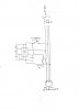
Using the circuit attached consisting of a momentary switch to supply 5v from the PAS supply lines to an NE555, wired as an astable oscillator, and to activate a relay to disconnect the signal line from the PAS to the controller, I have been able to mimic the PAS and energise the motor without having to turn the pedals.
The throttle is either On or Off, there is no intermediate control, but this exactly the same as the normal PAS.
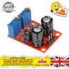
The NE555 was bought as a board from eBay for a little over £2 (see second attachment) and offers a wide range of signal frequencies and duty cycles using dip connectors and fine tuning using the variable potentiometers.
I have found a 7Hz frequency and a 55% duty cycle to be effective, but this does not need to be precise.
Many pedelecers while rarely requiring a throttle would welcome one for hill starts, for better accelaration at road junctions and to maintain movement while clipping in to the pedals.
E-bike kits will often have a facility to include a throttle so that the motor can be energised using either the bottom bracket PAS or the throttle.
In some instances it may be possible to fit a throttle to new preassembled bikes by connecting to the controller, but not all controllers will have suitable connection pads and in many instances the controller circuits will be encased in silicone to prevent water ingress thus preventing user access.
The PAS sensors fitted to many e-bikes rely on rotating magnets at the bottom bracket creating electronic pulses, in a Hall sensor, which energises the controller and activates the motor.
The first post of this thread provides an Arduino based circuit and code to create pulses to mimic those generated by the PAS and thereby activate the motor. I have spent some time trying to get this (and another Arduino based solution described in my recent post) to work without success.
Using the circuit attached consisting of a momentary switch to supply 5v from the PAS supply lines to an NE555, wired as an astable oscillator, and to activate a relay to disconnect the signal line from the PAS to the controller, I have been able to mimic the PAS and energise the motor without having to turn the pedals.
The throttle is either On or Off, there is no intermediate control, but this exactly the same as the normal PAS.
The NE555 was bought as a board from eBay for a little over £2 (see second attachment) and offers a wide range of signal frequencies and duty cycles using dip connectors and fine tuning using the variable potentiometers.
I have found a 7Hz frequency and a 55% duty cycle to be effective, but this does not need to be precise.