

no pal the pedal assist does not activate when you reverse pedal will do the test tomorrow and let you know the results thank you for all your help so farForgot yes you have a basic display some of then are digital but with no parameter changes.
Probe the 5v & Gnd to see you have about 5v, then probe Gnd & SIg and as you pass the magnet by the sensor voltage should switch. Typically could be anything between 0.6v - about 4v.
Just thought what happens when you reverse pedal does the PAS activate ?
motor problem
- Thread starter gazza19
- Start date
looks like it is the pedal assist ive seen the same one on ebay for 20 quid but also seen a much cheaper one without the led but with only 5 magnets instead of 12 is there a great difference in the way they work or would the five magnate one work just as good im thinking of putting it on the non drive side and just cutting the wire as dont know why they put them on the drive side too much to take off lolno pal the pedal assist does not activate when you reverse pedal will do the test tomorrow and let you know the results thank you for all your help so far
5 magnets just means the signal is slower so takes millisecond or three more to engage. Some 12 poles do give issues so 5, 8 or 10 work better.
thanks pal will order 5 magnet one then5 magnets just means the signal is slower so takes millisecond or three more to engage. Some 12 poles do give issues so 5, 8 or 10 work better.

thank you pal will look into itMeasure the BB width first so you know whether you need a 68mm or 73mm BB then you have to measure the current oa width of the BB axle as they come in various sizes. One them can get one for about £12.
From memory those Cyclematics have an unusual 95mm BB because of the controller box under the battery, so the axle is long, around 142mm. I used one from a scrap bike to fix my old Wisper 905, which was 90mm. I think there was 1 company in the US that sold them, but worked out to nearly £50, so was lucky otherwise the 905 would also have been unrepairable. If yours is still OK gazza, give it a regrease and make it last as long as poss.
Edit
Found 100mm sealed ones in the UK, if I'm correct about yours being 95mm, you would need 5mm of spacers to make it fit, poss on the non drive side to keep your chainline correct, although 2 +3mm would prob. work OK.
 Only one left!
Edit
Found 100mm sealed ones in the UK, if I'm correct about yours being 95mm, you would need 5mm of spacers to make it fit, poss on the non drive side to keep your chainline correct, although 2 +3mm would prob. work OK.
Neco Fat Bike Sealed Bottom Bracket - Square Taper - 100 x 151mm | eBay UK
Axle Length: 151mm. Complete with allen key crank bolts. Token Ninja Thread Fit Bottom Bracket - PF30 to Shimano 24mm Fit - BB841T-46. Weight: approx 440g. You may also like. General Info.
www.ebay.co.uk
Last edited:
thank you wheeliepete its just had new bearings put in but he said spindle could need replacing soon thats why i was thinking of changing to a sealed bottom bracket palFrom memory those Cyclematics have an unusual 95mm BB because of the controller box under the battery, so the axle is long, around 142mm. I used one from a scrap bike to fix my old Wisper 905, which was 90mm. I think there was 1 company in the US that sold them, but worked out to nearly £50, so was lucky otherwise the 905 would also have been unrepairable. If yours is still OK gazza, give it a regrease and make it last as long as poss.
Edit
Found 100mm sealed ones in the UK, if I'm correct about yours being 95mm, you would need 5mm of spacers to make it fit, poss on the non drive side to keep your chainline correct, although 2 +3mm would prob. work OK.
Only one left!Neco Fat Bike Sealed Bottom Bracket - Square Taper - 100 x 151mm | eBay UK
Axle Length: 151mm. Complete with allen key crank bolts. Token Ninja Thread Fit Bottom Bracket - PF30 to Shimano 24mm Fit - BB841T-46. Weight: approx 440g. You may also like. General Info.www.ebay.co.uk
hi pal it was the pedal assist that had gone the new one has come and just put it the crank to try it and the motor turns so its just the brakes i need to sort now on the controller side the wires are black and grey on the brake side they are blue and red do you know what colour would go to what as i just want to open it one more time and connect the brake switches then close it and leave it lol thanks for any advice palthanks pal will order 5 magnet one then
there is a picture on here somewhere of themhi pal it was the pedal assist that had gone the new one has come and just put it the crank to try it and the motor turns so its just the brakes i need to sort now on the controller side the wires are black and grey on the brake side they are blue and red do you know what colour would go to what as i just want to open it one more time and connect the brake switches then close it and leave it lol thanks for any advice pal
Right guys im banboozled ive put new controller in new brakes and pedal assist the motor makes the noise as tho it’s working when you pedal and shuts off when the brakes are applied but the wheel dosnt engage and spin unless ur pedalling but it doesn’t speed up so I’m wondering if it could be the cable from the controller to the the motor connector and how to test itFor 2 wire brake if they don't work just switch the wires.
The cable will be fine all you can do is carry out a continuation check on the wiring.
What is likely happening is that with the new controller motor halls and phases are out of sync so one has to change the wire positions, to do so you need block connectors. If you have motor halls then there are 36 possible different wire combos to test and maybe up to six may work, then you seclect the combo that works the best.
Motor wire chart.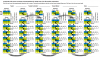
That sounds well complicated don’t think il be able to do that so might have to end selling it could the halls be ok and one of the phaze wires need swapping aboutThe cable will be fine all you can do is carry out a continuation check on the wiring.
What is likely happening is that with the new controller motor halls and phases are out of sync so one has to change the wire positions, to do so you need block connectors. If you have motor halls then there are 36 possible different wire combos to test and maybe up to six may work, then you seclect the combo that works the best.
Motor wire chart.View attachment 44350
AlThat sounds well complicated don’t think il be able to do that so might have to end selling it could the halls be ok and one of the phaze wires need swapping about
That sounds well complicated don’t think il be able to do that so might have to end selling it could the halls be ok and one of the phaze wires need swapping about
[/QUOTE
im sounding a bit thick here but what do i do with the terminal block do i have to completely put all the hall wires from the controller into them and the motor connector also when i connect the intelligent wire the motor spins as always your expertise is more than valuable to me im learning more than i ever could trying to do it myself
It looks complicated but in reality it is very simple step by step chart process to follow, you do need block type connectors or bullet type connectors and not the water proof type at the controller end to carry out the wire swapping. Often it's a combo of both the hall and phase that is out of sync. One simply follows the chart and on a separate sheet number 36 lines to write down the results of each test as indicated in the white tick boxes, once all have been tested one then re - tests the best 3,4,5 or 6 results and goes with that one. In all about 1/2 hour it takes and no meter is needed.
When done keep the record of results in case a test ride shows up an issue so one would make a note on the sheet and try another good result, it is the only way to go.
Your issues are likely as the controller is a different brand so the syncing can often change, it is a long winded way of doing the self learn wire procedure that some controllers have. You are better off buying a brainwave or other cheap china controller that has that procedure to automatically sync the phase and halls.
now i am def thick lol as i still dont know what to do with the blocks do you have a diagram or anything showing me what to do with it please. This controller i have has two green intelligent wires that when connected makes the wheel spinIt looks complicated but in reality it is very simple step by step chart process to follow, you do need block type connectors or bullet type connectors and not the water proof type at the controller end to carry out the wire swapping. Often it's a combo of both the hall and phase that is out of sync. One simply follows the chart and on a separate sheet number 36 lines to write down the results of each test as indicated in the white tick boxes, once all have been tested one then re - tests the best 3,4,5 or 6 results and goes with that one. In all about 1/2 hour it takes and no meter is needed.
When done keep the record of results in case a test ride shows up an issue so one would make a note on the sheet and try another good result, it is the only way to go.
Your issues are likely as the controller is a different brand so the syncing can often change, it is a long winded way of doing the self learn wire procedure that some controllers have. You are better off buying a brainwave or other cheap china controller that has that procedure to automatically sync the phase and halls.
Related Articles
-
 MTF Enterprises announces acquisition of EMU Electric Bikes
- Started by: Pedelecs
-
 Wisper 806T folding bike wins Which? ‘Best Buy’
- Started by: Pedelecs
-
 Sustrans calls for protected cycle lanes
- Started by: Pedelecs
-
 Amazon launch their first UK e-cargo micromobility hub
- Started by: Pedelecs
