Pedelec Function - How it works and how to configure it

jerrysimon

Esteemed Pedelecer
Aug 27, 2009
3,292
112
Cambridge, UK
Ok being a throttle jockey for the last two plus years my latest project is pedelec only and I am pretty sure the controller is specific to the motor plus does not support throttle.

Here is how I understand the pedelec function.

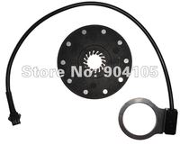
1. The circular rotating disk with magnets in it


a) A rotating disk with magnets in it goes on the BB (Bottom Bracket) fitting crank shaft. I have put mine on the drive side. Does it matter which side ?

b) Why do some have more magnets than others ?

c) Can different pedelec fittings be interchanged and used with different controllers or are they controller specific in terms of design and number of magnets fitted etc ?

d) This one has to be placed with magnets facing in to the bike frame.


2. The sensor


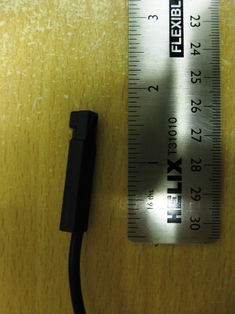
a) Fits to the frame, has a cable (three wires) which goes back to the controller and detects pedal cadence speed. Do they all have three wires ?

b) Seems very sensitive as to how close it is placed to the the rotating disk (as shown below if place more than a 2-3mm away it does not work) and if it is underneath or above the bottom bracket. On mine if I place it underneath it works fine when pedaling clockwise if placed on top of the BB it ONLY works when pedaling backwards ?

c) Even fitted on the bottom of the BB it you pedal backwards hard it will engage the motor as well ?

Diagram showing fitting (courtesy of poster laroche).


I have to admit setting up pedelec over a basic throttle only option is much more challenging.

PS are there instructions or a web page somewhere that details the fitting of a pedelec function and how it works electronically ? Maybe even a post on here ? I did search for one.

Regards

Jerry
 
Last edited:

flecc

Member
Oct 25, 2006
52,763
30,349
They vary Jerry. They can be birectional, just signalling pulses either way to give power, or unidirectional which means the disc must be on the correct side for forward pedalling to give the signals. Some use the pass rate to signal power phase down and/or assist limit cut-off, so the number of magnets is significant on those. With that type every other magnet can sometimes be removed to double the assist speed limit. The sensor must be the right side of the disc for the Hall sensor to get the right magnet polarity to read, but it doesn't matter whether the sensor is above or below the bottom bracket. The Hall sensor has three wires, Positive and Negative voltage (usually 5 volts) and Signal.
 

laroche

Pedelecer
Apr 16, 2012
30
0
The 2-3mm gap limit puts me off a carbon frame for mine (sod it!). Inevitably on such bikes, there's a build-up of material on the underside of the BB (which isn't always horizontal, L to R, either) that could well result in the gap being too big. Bromptons, with steel BB shells, offer 'naturally' narrow gaps. What, I wonder, about aluminium?

I'm leaning to steel....and beginning to hate that sensor!


Hang on a minute. The disk is 41mm diameter. The 'standard' BB shell is about 35mm with outside diameter bigger than that depending on the wall thickness of the material, but unlikely to reach 41mm - with the possible exception of carbon. The disk looks bigger than the BB shell on my Trek for eg. That would suggest the problem to be getting the sensor far enough away, rather than close enough, to obtain the right gap. Is that what you found Jerry?
 
Last edited:

jerrysimon

Esteemed Pedelecer
Aug 27, 2009
3,292
112
Cambridge, UK
Hmm looking at this I can see how fitting this behind the BB retaining ring would be a lot easier than gluing it to the bottom of the frame BB casing.


I wonder are these units compatible across different controllers ?

I guess you would have to get one with the same number of magnets etc. I have managed to fit the stock one using 5 min epoxy. The glue strip it is supplied with is next to useless!

Regards

Jerry
 

dingrpdl

Pedelecer
Apr 21, 2012
78
16
Hong Kong
I guess you would have to get one with the same number of magnets etc.
This one has 8 magnets as opposed to yours with 10 magnets. I guess that just means that you have to be pedalling 25% faster on this one for the motor to cut in (and for each incremental power step-up).

I have seen another solution in another website (sorry I don't have the link) where magnets were epoxied onto the chainring itself and the sensor mounted appropriately. That way, there is was need to take the crank and/or chainring off to mount the plastic disc with the embedded magnets.

Richard
 

paulhipwood

Pedelecer
Feb 12, 2012
77
1
Halesowen
My sensor (magnet disc), senses on the face of the rotor not the edge of the rotor.
If you have it this way then it can "see" the magnet directly, without having the plastic outer edge interfering.
 

jerrysimon

Esteemed Pedelecer
Aug 27, 2009
3,292
112
Cambridge, UK
Thanks Richard.

Yes Paul that occurred to me too.

I did find another one with ten magnets.


I have also asked the supplier, Tongxin, to see if they have any instructions about how to fit their sensor and suggested that their design may limit fitting on some bikes.


Regards

Jerry
 

daniel.weck

Esteemed Pedelecer
Aug 8, 2009
1,224
1
I'm just discovering this thread, so for reference, here are some pictures of my temporary-fitted pedelec sensor (this was at the time of build, it is now secured with plastic straps, and covered in black electrician tape):


Woosh

Trade Member
May 19, 2012
19,406
16,387
Southend on Sea
wooshbikes.co.uk
Hi Jerry,

I am not technical but I've been told that you can mount the pedelec disc on either side of the bottom bracket.
When the disc is on the opposite side, the sensor faces the opposite pole on the disc but because its own polarity is also reversed (for being mounted on the 'wrong' side), the output is the same.

If you want another pedelec disc and sensor to try out, PM me and I'll be pleased to send you one.
 

jerrysimon

Esteemed Pedelecer
Aug 27, 2009
3,292
112
Cambridge, UK
Thanks Hatti,

I actually have a spare coming from the supplier and have also ordered two stock sensor kits from Outrider.

As can be seen by my other post I have now successully fitted the sensor on my Bromptons left side.

Dan, when I mounted my sensor, as you have yours mounted about the BB, on the crank (right) side the motor would only work if I spun the pedals backwards. I can now mount it like yours since I have moved it to the left non crank side.

Regards

Jerry
 

neptune

Esteemed Pedelecer
Jan 30, 2012
1,743
353
Boston lincs
I have theory as to why sensor spacing is so critical on some setups. If the magnets were stronger, then they would trigger the sensor at a greater distance. However, the fields of adjacent magnets would then interfere with each other, so that there would be no null points between magnets to allow the sensor to switch off between pulses. So therefore the only way we could use stronger magnets would be to have a larger magnet wheel. The design, as with most designs ,is a compromise.