
Remove 15mph speed limiter
- Thread starter spikey
- Start date
D
Deleted member 4366
Guest
You'd need to post a picture of your controller with all the wires laid out showing all the connectors to be sur. The KU65 or S06S or S06P from BMSBattery will probably work, but you'd need to change a couple of connectors.
slightly off topic but has anyone used dc-dc boost converters instead of extra batteries. I seem to remember thinking that if you have a brushed motor you might be able to add one on the output from the controller to raise from 36 to higher volts for more rear wheel rpm at the expense of battery range. Sadly I am not electronically minded enough to be able to fathom the calculations needed to establish whether this would work.
10A 12V~80V DC-DC Boost Converter Power Supply 500W 600W Voltage Regulator | eBay
this sort of thing.
10A 12V~80V DC-DC Boost Converter Power Supply 500W 600W Voltage Regulator | eBay
this sort of thing.
I just bought this bike at a cheap store here in Norway, and after taking apart the controller I concluded we have the same controller.. and good news: I HAVE SOLVED THE MAX SPEED DEACTIVATION BLOCK!
Now, what you do is this:
1. disassemble your controller
2. take a jumper (like those behind old CD/DVD-Drives, or something else to short the two pins marked 'enactment' (see pictures below)
3. While pins are shorted, turn on the power on the battery for a couple of seconds and turn it off again.
4. Remove the jumper or material used to short-circuit the 2 pins and fire up the bike and go for a test-spin without boundaries ;D
That's it; you now should have your motor running even downhill.
Though it don't go -much- faster on flat ground, it gets more motivating to pedal faster to see how fast one can go with a little help") and with the limits at 25kph here in Norway, I can actually feel the difference even on my 200W 24V engine Biking just got EVEN more fun!!
and with the limits at 25kph here in Norway, I can actually feel the difference even on my 200W 24V engine Biking just got EVEN more fun!!
By the Way; One can easily connect a cable to those two pins, to make a more permanent switch on the handle-type-of-solution.. That way, you can keep it legal.
200W is still a bit embarrassing in steep hills, so I will try to solder on some soldering iron to see if that fixes that problem as well... I will let you know, if I feel the result worth mentioning.
Sorry for posting on a partially dead link, but I could not find this info anywhere online, so maybe someone reads this and save themselfes some time and frustration Great post neither way, I have learned a lot here
Now, what you do is this:
1. disassemble your controller
2. take a jumper (like those behind old CD/DVD-Drives, or something else to short the two pins marked 'enactment' (see pictures below)
3. While pins are shorted, turn on the power on the battery for a couple of seconds and turn it off again.
4. Remove the jumper or material used to short-circuit the 2 pins and fire up the bike and go for a test-spin without boundaries ;D
That's it; you now should have your motor running even downhill.
Though it don't go -much- faster on flat ground, it gets more motivating to pedal faster to see how fast one can go with a little help
and with the limits at 25kph here in Norway, I can actually feel the difference even on my 200W 24V engine Biking just got EVEN more fun!!By the Way; One can easily connect a cable to those two pins, to make a more permanent switch on the handle-type-of-solution.. That way, you can keep it legal.
200W is still a bit embarrassing in steep hills, so I will try to solder on some soldering iron to see if that fixes that problem as well... I will let you know, if I feel the result worth mentioning.
Sorry for posting on a partially dead link, but I could not find this info anywhere online, so maybe someone reads this and save themselfes some time and frustration
Great post neither way, I have learned a lot here Hi Kaare,
Great post - thanks for the info! I'll check my controller tomorrow. Out of interest, what brand is your bike? EcoRide? (Swedish/Chinese).
Mvh from Sweden
Great post - thanks for the info! I'll check my controller tomorrow. Out of interest, what brand is your bike? EcoRide? (Swedish/Chinese).
Mvh from Sweden
Hi!
I bought it at "Biltema" and after a quick biltema.se search I found the same bike there (nice with global stores and products sometimes).
http://www.biltema.se/sv/Fritid/Cykel/Cyklar-och-vagnar/Elcykel/Elcykel-folding-20-271401/
If you wonder why your wires don't go to the same pins on the board, don't worry about it. As long as the board has the same model number (or even if it don't but has the same 'enactment'-pin on the board), this procedure is 100% safe.
Last edited:
Hi again,
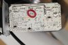
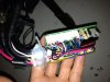
I opened up my controller today but couldn't see the "enactment" pin. The board is tiny as you know, and feels quite fragile so I didn't dare to poke about too much or start crossing out connections, just in case...
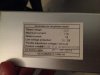
The model number is similar however. Yours seems to be LSW70A6G whilst mine seems to have an extension of this: LSW70A6G-V02-13083
The bike is an Ecoride. The motor is a standard 250w brushless 8Fun hub motor and battery is 36v 10Ah - all Chinese of course.
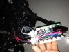
Are you able to locate the "enactment" pins in these photographs?
I opened up my controller today but couldn't see the "enactment" pin. The board is tiny as you know, and feels quite fragile so I didn't dare to poke about too much or start crossing out connections, just in case...
The model number is similar however. Yours seems to be LSW70A6G whilst mine seems to have an extension of this: LSW70A6G-V02-13083
The bike is an Ecoride. The motor is a standard 250w brushless 8Fun hub motor and battery is 36v 10Ah - all Chinese of course.
Are you able to locate the "enactment" pins in these photographs?
Last edited:
D
Deleted member 4366
Guest
Yours is different. It doesn't have the jumper in the same place. It might use an external jumper. Is there a pair of single white wires, which are joined by small black connectors outside of the controller?
No, the only external wires joined with black plastic connectors outside the controller is connection #1 (6 km/h no-pedalling throttle limiter), and the front and rear lights.
This is the connection diagram. http://store.ecoride.se/EcoRidekopplingsschema2.pdf
Connection #1, the 6km/h speed limiter, is for the throttle control only. Disconnecting that means that the bike will go up to 25 km/h without the need for pedalling. The 25 km/h limiter still kicks in though. So I keep these plugs connected, as not pedalling up a hill at 25 km/h looks suspicious...
Basically, I want to remove the 25km/h limiter because the bike really pulses when cykling on flat ground around the limit. The motor kicks in and out, and it's very annoying over longer distances.
Any other suggestions?
Hi again. d8veh is right. yet as he say, the jumper points might still be there, just not labeled., Can't see any jumper wiring, but if there where, that would be the point, so stretching the side plate further out on the wire to get room to examine further would be good (though be very gentle, especially the first time, since they are glued/silicon'd together with the rubber surroundings)..
Don't know what Connector 6 is supposed to do, but I would try !! AT YOUR OWN RISK !! to disconnect it and power up (due to my trial and error nature, but can't see how that should blow anything up .. did a fast google search on your version of the board, but couldn't find anything in a hurry.
<edit>
I now see that you have a throtle walking pedal override that limits to 6km/h.. could this curcuit give you any hints to how the limiter works? This might be a "golden plate" in this regard.. !
I see some more tonight when I get some nerding time ;D
I also have a wiring diagram of the whole card layouts of all models, I just need to figure out where I put it Then I can compare it with mine, to figure out if, and if so, where the enactmen pins are
Don't give up on it yet
Another thing to try, though a bit of a stretch, is to short every solder point fairly close together on the board (one at a time) (WHILE BATTERY NOT CONNECTED), since some jumpers tend to erase some information in memory, so the power is not actually needed for the change. If you are lucky, that would trigger off the limiter upon next bootup. But as I say, this is stretching science a bit, and you are now entering the world of real old school hacking hehe
I also would suspect such a circuit to need some sort off battery(?) which I cannot see on this boards but hey, I have seen stranger things working than that
-Kaare
Don't know what Connector 6 is supposed to do, but I would try !! AT YOUR OWN RISK !! to disconnect it and power up (due to my trial and error nature, but can't see how that should blow anything up
.. did a fast google search on your version of the board, but couldn't find anything in a hurry.<edit>
I now see that you have a throtle walking pedal override that limits to 6km/h.. could this curcuit give you any hints to how the limiter works? This might be a "golden plate" in this regard.. !
I see some more tonight when I get some nerding time ;D
I also have a wiring diagram of the whole card layouts of all models, I just need to figure out where I put it
Then I can compare it with mine, to figure out if, and if so, where the enactmen pins are Don't give up on it yet
Another thing to try, though a bit of a stretch, is to short every solder point fairly close together on the board (one at a time) (WHILE BATTERY NOT CONNECTED), since some jumpers tend to erase some information in memory, so the power is not actually needed for the change. If you are lucky, that would trigger off the limiter upon next bootup. But as I say, this is stretching science a bit, and you are now entering the world of real old school hacking
heheI also would suspect such a circuit to need some sort off battery(?) which I cannot see on this boards
but hey, I have seen stranger things working than that -Kaare
Last edited:
D
Deleted member 4366
Guest
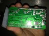
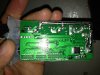
I'm looking at the back of the PCB at all the connections along the edge. They have various markings:
V0 is 5v
GND is 0v
12V is 12V.
H1, H2 and H3 are the hall signals.
All the ones beginning with D must be data inputs from brakes, display, PAS and throttle, plus some unused ones.
For the ones marked beginning with a D, can you tell me the markings of those with wires in, and what the wires go to? Then can you list the unpopulated ones.
Are there any other markings not mentioned above? There should be another one beginning with V for the battery voltage to the display. I can't read the ones where the light is shining on it.
D
Deleted member 4366
Guest
Connector 6 is for the lights. It carries battery voltage, so don't plug it in to anything else, and don't short it out.Don't know what Connector 6 is supposed to do, but I would try !! AT YOUR OWN RISK !! to disconnect it and power up (due to my trial and error nature, but can't see how that should blow anything up
Hi Kaare and d8veh,
Thanks for your replies. Just got in after a long day out - about 35km on the bike as well...and still feel the pulsing motion kinda like sea-sickness!
It's late now, but I will go down in the morning and take some more pictures and try to answer your questions d8veh about the markings on the wires and where they go to etc.
I'll also try to short out the board with the battery disconnected Kaare, just in case
Thanks - will report back tomorrow
D
Deleted member 4366
Guest
Don't do that until we've figured out what's what. Shorting out some wires or pads on the PCB, can instantly damage the controller.I'll also try to short out the board with the battery disconnected Kaare, just in case
Ok - I haven't crossed anything out yet.
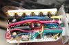
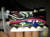
I opened up the controller again and took a few more pictures.
It's very hard to know exactly where everything goes, but I've managed to figure some things out. I made some notes on one of the pictures below.
There doesn't seem to be any jumpers on the circuit board at all, except something that looks like a tiny single jumper (ie. it doesn't look like it is connecting to poles, rather, just a single pole with a piece of plastic slid down it). You can (almost) see it on the second image, between the light brown upright capacitior, and the white sockets (where my far left red arrow is pointing), but it is so tiny, I didn't dare to touch it. I'd need a pair of fine tweezers to get to it anyway.
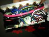
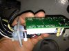
Does this help in any way?
I opened up the controller again and took a few more pictures.
It's very hard to know exactly where everything goes, but I've managed to figure some things out. I made some notes on one of the pictures below.
There doesn't seem to be any jumpers on the circuit board at all, except something that looks like a tiny single jumper (ie. it doesn't look like it is connecting to poles, rather, just a single pole with a piece of plastic slid down it). You can (almost) see it on the second image, between the light brown upright capacitior, and the white sockets (where my far left red arrow is pointing), but it is so tiny, I didn't dare to touch it. I'd need a pair of fine tweezers to get to it anyway.
Does this help in any way?
I'm guessing that the motor sends signals back to the controller to say something like how many RPM it's doing, or, how many volts its using?
I wonder if it is just a matter of finding the cable sending this info back to the controller, and disconnecting it on the circuit board?
This would explain the pulsating feeling - going over and under the programmed limit - on flat ground at around 24 - 25km/h. Or am I way off here?
I wonder if it is just a matter of finding the cable sending this info back to the controller, and disconnecting it on the circuit board?
This would explain the pulsating feeling - going over and under the programmed limit - on flat ground at around 24 - 25km/h. Or am I way off here?
D
Deleted member 4366
Guest
Some motors have an addition wire that gives a speed signal, but some controllers don't need it. They can get the speed from the normal hall sensors.
I think that the information that you've given above regarding which wires go where are incorrect. Can you use a meter on beep to check between the connector and the pad on the PCB.
I've decoded some more connections:
V0 is 5v
GND is 0v
12V is 12V.
H1, H2 and H3 are the hall signals.
VIN is battery voltage
VKEY is the return from the switch that powers the controller with battery voltage
I need to know which ones the throttle, PAS, brakes, and control panel are connected to.
I'm guessing DBK is the brake signal and DVP is PAS
If any, DSM looks like the best candidate: Data - Speed Modulation maybe.
Ok. I don't have a meter unfortunately, but I wonder if it could be an idea to simply unplug one wire at a time, starting with the DSM you mention above, and see what happens?
D
Deleted member 4366
Guest
As far as I can see, there's nothing connected to DSM, so the idea is to short it to ground. If you put a 1K resistor between them, it''ll give an extra level of protection. You can buy a 1/4W 1K resistor for nearly nothing from an electronics supplier.
With everything open and switched on, get a friend to hold the wheel off the ground and spin the motor up to the maximum with the throttle or PAS. While it's running at full speed, touch one end of the resistor to ground and the other to DSM and any other likely data pads to see if the motor increases in speed.
With everything open and switched on, get a friend to hold the wheel off the ground and spin the motor up to the maximum with the throttle or PAS. While it's running at full speed, touch one end of the resistor to ground and the other to DSM and any other likely data pads to see if the motor increases in speed.