Running additional circuits off main battery

103Alex1

Esteemed Pedelecer
Sep 29, 2012
2,228
67
Never done this before so .... trying to get my head around how you actually run additional circuits off your bike battery in terms of where the wires are taken off from and whether you need some kind of junction box or splitter inserted.

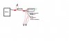
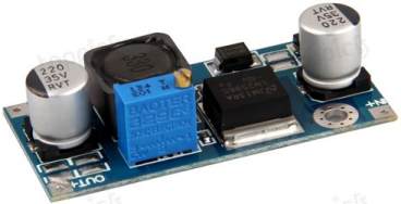
At the moment my setup will look like this before taking off a (likely) 9v supply and a 12v supply, each via its own step-down converter with heatsinks :

http://www.pedelecs.co.uk/forum/electric-bicycles/13759-bridge-battery-controller-4.html#post168025

I've yet to insert the toggle switch to isolate the controller but have all the parts ready.

Guess I'll need 2 more switches :eek: - one for isolating the lighting circuit and another for isolating the 12v accessory circuit.... (and a 3rd for the cruise control !). Bought 5 4110 MOSFETs but think I may need more !

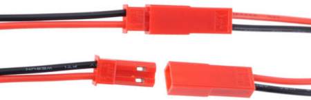
Can anyone show / tell me where and how I actually take the 2 new supplies off from the battery, in the context of d8veh's crystal clear diagram linked above ... and how these parallel supplies then get isolated from the battery to stop them drawing trickle power ? I am envisaging having to swap out the Deans connectors for a 3-way supply connector or something like that :confused:. Am presuming the split is done before the controller (it's a KU123).

If it's relevant this is the socket system and inline fuse holder I have ordered for the 12v accessory circuit and waiting to be delivered ...

Waterproof Lighter Power Socket Locking Plug Boot 12 Volt Marine Motorcycle | eBay

Special Listing to Add An Inline Fuse Holder When Purchasing A Socket Product | eBay
 
Last edited:
D

Deleted member 4366

Guest
In principle,it's quite easy. There's lots of ways to achieve it in terms of how you join the wires and where you make the junctions. but it should look something like this:
 

Attachments

Alan Quay

Esteemed Pedelecer
Dec 4, 2012
2,351
1,076
Devon
As for joining wires, crimping is probably the best/easiest/quickest method. Make sure you a use a decent ratchet crimper though.
 

Haku

Esteemed Pedelecer
Jun 20, 2007
339
4
Gloucestershire
I'm going to do a 3rd incarnation of my bike light setup powered from the bike's battery and wanted more light (360 LEDs is not enough ;)), so with that in mind I decided to upgrade things with a microcontroller with more IO pins to control more lights and be able to make the back light continually fade between 50%-100%-50% brightness instead of 100% all the time, along with a higher powered voltage regulator to cope as the current one I'm using is very good but can only output up to 10 watts and it's at it's limit.

I bought one of these variable output switching regulators to test:

as it was cheap and promised 2A output and 3A with heatsink, I was only looking for about 15 watts output but during testing of putting 17 watts through it I found the entire board got so hot you couldn't touch it! So I'll be using Dimension Engineering's 25watt regulator which is more compact and only gets a bit warm when you put that amount of power through it.

I tapped into the bike's battery by soldering one of these JST connectors onto the base connection the battery sits on:

There's lots of these pre-wired JST connectors cheap on eBay.

On/off switch? Nah never fitted one, my lighting circuitry runs all the time when the battery's switch is on and the power draw is so low that it's not worth bothering about. I did once hookup my bench power supply to my bike and was a bit surprised to find that its controller draws 2 watts whilst just sitting there switched on and doing 'nothing'.

In the next version of the lighting controller I'm going to put a small LCD screen to display battery voltage and ambient temperature. One day I'd like to build one that can measure+calculate+display the relationship between watts used and mph.
 
Last edited:

Alan Quay

Esteemed Pedelecer
Dec 4, 2012
2,351
1,076
Devon
Funny, I just melted my dc-dc converter, which is basically the same as the one in the picture. Not a lot of load, but I suspect 38v is a bit much for the 35v caps.
 

103Alex1

Esteemed Pedelecer
Sep 29, 2012
2,228
67
In principle,it's quite easy. There's lots of ways to achieve it in terms of how you join the wires and where you make the junctions. but it should look something like this:
OK that's really helpful - basically what my mind is fixing on first off is that I may need to swap out the Deans Connectors for something more suitable for taking 3 wires off each pole - one each to the two new DC converters and the other to the controller.

I could only just fit one 12AWG wire on a Deans connector pole so soldering 3 wires to the same terminal seems like an order a bit too tall ! I thought I'd need something like a junction box at that point to be honest .. what are the options ?
 

103Alex1

Esteemed Pedelecer
Sep 29, 2012
2,228
67
As for joining wires, crimping is probably the best/easiest/quickest method. Make sure you a use a decent ratchet crimper though.
Hi Mike - I keep avoiding this owing to the ridiculous prices I keep getting quoted - the latest one from RS was £348 and not found any below about £25. What's really getting to me is that a combined wire stripper and crimping tool for household electrics is about £5. When the tools cost that much one starts heating up soldering irons (which I already have) ! Are there any sensibly priced good quality crimping tools for this sort of work ?

Not forgetting of course to add a few of these at relevant points..

.... an in-line fuse holder ? (dusts off shoulders with pride at the thought of recognizing a part at last .... let's hope it doesn't come before a fall :eek:)
 

103Alex1

Esteemed Pedelecer
Sep 29, 2012
2,228
67
I bought one of these variable output switching regulators to test:

as it was cheap and promised 2A output and 3A with heatsink, I was only looking for about 15 watts output but during testing of putting 17 watts through it I found the entire board got so hot you couldn't touch it!
Was that one like these ... :eek:

LM2596HV DCDC Step Down Converter Adjustable Heatsink | eBay

Just noticed it says output power 10W or less on that one ..

So I'll be using Dimension Engineering's 25watt regulator which is more compact and only gets a bit warm when you put that amount of power through it.
I'm still struggling to work out how many Watts running say 3 CREE XML-T6 lamps in parallel would output and how much current they would draw. Don't want to flatten my battery running too high a current :confused: .. and they seem to be able to run at up to 3A which would cause a problem (although I can't quite work out why / how this is yet - still a bit muddled by it all but very slowly getting there ... perhaps you could help explain more in laymans' terms ? :) ..

For some reason I am thinking I mustn't exceed 0.75A current for any light or combination of lights in series or the draw on my battery will start to get significant ..

So I'll be using Dimension Engineering's 25watt regulator which is more compact and only gets a bit warm when you put that amount of power through it.

On/off switch? Nah never fitted one, my lighting circuitry runs all the time when the battery's switch is on and the power draw is so low that it's not worth bothering about. I did once hookup my bench power supply to my bike and was a bit surprised to find that its controller draws 2 watts whilst just sitting there switched on and doing 'nothing'.
Looked at that DC-DC converter and it seems a good product especially not getting so hot. However, my battery is 36V and they look like they are only good for input up to 35V albeit output can be up to 3A. Am still a bit terrified of building in the step-down converters and then finding they run hot or blow out and damage my battery or controller and wiring.

This one looks like it's designed for high voltage input but is rated only to 1A on the output :( :

Adjustable step down switching voltage regulator

One of these accepting higher voltage input and running cool would seem to be the best option ?

Funny, I just melted my dc-dc converter, which is basically the same as the one in the picture. Not a lot of load, but I suspect 38v is a bit much for the 35v caps.
Oops !
 

Alan Quay

Esteemed Pedelecer
Dec 4, 2012
2,351
1,076
Devon
How about keeping the Deans connector, cutting the 12awg cable and crimping an inline into it, with a smaller wire in addition to supply the voltage converters. The small wire probably only needs to supply 1A, to both voltage converters (you would need to work out how much current to be sure).
Another alternative is the old 'scotch lock' connector. These have the advantage of not cutting the main (high current) wire. They are a bit of a fiddle though.
 

Alan Quay

Esteemed Pedelecer
Dec 4, 2012
2,351
1,076
Devon
Sorry, missed last few posts.

£25 from maplin sounds about right for a reasonable crimper. A tool worth having though if you are going to tinker with electricals on vehicles.

I just ordered a new dc-dc converter today:

LM2596 DC-DC Step Down Adjustable Power Supply Module Buck | eBay


Oh, and your self imposed 0.75A Limit, I presume this is at 36v, giving you a total of 27W (including losses) to play with?
 
Last edited:

103Alex1

Esteemed Pedelecer
Sep 29, 2012
2,228
67
Sorry, missed last few posts.

£25 from maplin sounds about right for a reasonable crimper. A tool worth having though if you are going to tinker with electricals on vehicles.

I just ordered a new dc-dc converter today:

LM2596 DC-DC Step Down Adjustable Power Supply Module Buck | eBay


Oh, and your self imposed 0.75A Limit, I presume this is at 36v, giving you a total of 27W (including losses) to play with?
My tool expenditure is running into the hundreds of pounds now and won't be using most of the stuff once my bike is built so need to be sensible about buying lots of tools for one job. I'll buy one if I have to (still resent paying 5 times what you can get the same thing with bigger crimp slots tho' ... complete exploitation :mad:) ... but are crimp connections better than soldered ones ? :confused:

The self-imposed limit is nothing more than reading somewhere that drawing <1A per light or accessory run off an installation means you can effectively run 5 or 6 lights, phones opn charge etc. etc. all off your bike and hardly draw any power but if you start running lights etc. at over an amp then there is suddenly a huge demand on your battery which you will notice in having your range hammered. I'm still trying to work out how that is... don't understand this yet !

Very simply, I'm trying to make/buy XML- T6 and 3W(ish) rear light accessories that can be made to run off my bike from a handlebar control switch rather than controlled at the light unit and be turned on sequentially via a high/mid/low beam switch. Importantly, using negligible battery capacity, and also being able to simultaneously run my mobile phone, maybe charge my electronic cigarette batteries on the move etc etc off my accessory circuit.

I had just picked up that if you increase the amps you run the lights at that somehow they become massively greedy and you'll run down your bike battery noticeably. A week ago I thought that if I drew 10A for my lights there would be that much less available for the motor and operating the bike. Electrics are REALLY confusing from a zero background of theoretical knowledge !
 

Old_Dave

Esteemed Pedelecer
Sep 15, 2012
1,211
2
Dumfries & Galloway
but are crimp connections better than soldered ones ?
No...but they are quicker and depending on the connector are also insulated, thus another bit of time saved.

dusts off shoulders with pride at the thought of recognizing a part at last
:D

I had just picked up that if you increase the amps
To save confusion with the effect of amps at different voltages, maybe better to calculate every thing in watts (volts x amps) to get more meaning full time number and an idea of how much your battery is effected.. sure it dosen't take losses into account but its as close a number as you will need.
 
Last edited:

Alan Quay

Esteemed Pedelecer
Dec 4, 2012
2,351
1,076
Devon
... but are crimp connections better than soldered ones ? :confused:
Crimp connectors don't suffer so badly from long term vibration fatigue problems. Soldered connection on a board aren't too bad, but where there is no strain relief for the cable (eg inline connections), you can get problems. That said, I expect well soldered joints correctly protected would be ok.

Electrics are REALLY confusing from a zero background of theoretical knowledge !
It important to understand that 1A at 36v is the same amount of power as 10A at 3.6v - Both = 36W

When you are considering the amount of energy in the battery, you will probably talk about it as Ah - eg 20Ah. So, if you are using 1A at 36v, you are using 1/20th of your available energy for the lights. if those lights were running through a 100% efficient buck converter, at 3.6v, you would be able to pull 10A through them (assuming you converter were capable)

At 1A from the battery, I would imagine the effect on performance to be negligible, since the controller/motor will be the limiting factor in current draw. Only the range will be affected (1/20th less).

Hope that makes sense.
 

Scimitar

Esteemed Pedelecer
Jul 31, 2010
1,772
40
Ireland
Another alternative is the old 'scotch lock' connector. These have the advantage of not cutting the main (high current) wire. They are a bit of a fiddle though.
Scotchloks are fine in the right place - like a quick and dirty job just to get the car out of the door, but not for anything you want to be reliable, especially lights.
 

Scimitar

Esteemed Pedelecer
Jul 31, 2010
1,772
40
Ireland
I had just picked up that if you increase the amps you run the lights at that somehow they become massively greedy and you'll run down your bike battery noticeably. A week ago I thought that if I drew 10A for my lights there would be that much less available for the motor and operating the bike. Electrics are REALLY confusing from a zero background of theoretical knowledge !
It's quite linear - if you draw 1A for your lights you'll deplete your main battery by a third of what you would if you draw 3A. The lights don't suddenly get greedy, unless you mean that you've read that some LEDs at full power will draw a disproportionate amount of current compared to half-power, say. I'd not worry about that - simple rule is not to run any LED at full power anyway, as it will blow itself up in short order as most heatsinking is inadequate.
 

Alan Quay

Esteemed Pedelecer
Dec 4, 2012
2,351
1,076
Devon
Scotchloks are fine in the right place - like a quick and dirty job just to get the car out of the door, but not for anything you want to be reliable, especially lights.
I agree that's the impression, but correctly sized, installed and protected they are more reliable than you would think. Often though, I agree that they are installed poorly and will fail.