About a day after first installing my hub kit I was chatting with a chap over on pedelec.de who suggested a new controller would be a good idea and i bought one.. well it turns out my bike performs just fine and after an initial pas hicup (wrong sensor type for my bike) I cant fault it beyond a general gripe about the closed nature of the controller config, with the only parameter i am able to configure is the metric used for the display. But the bike works great ") Yes on some very select smooth tracks i could use a bit more speed, but as it stands 15mph is a bit too fast for many rds with my bike..
Yes on some very select smooth tracks i could use a bit more speed, but as it stands 15mph is a bit too fast for many rds with my bike..
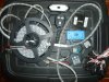
So I have this controller 22a peak power, KTlcd10 headset, ive got a nice big controller box that i can squeeze in between my 2x dropped crossbars (see profile pic) under the battery/existing controller. @saneagle has given me the circuit for a battery isolating ignition switch to fill the hole in the box.
And i have a backburner idea of establishing a bike area network(BAN) from bits out of the old projects box... that looks like it too could live in the big controller box as well,, hmmmm
stage1 after establishing the network will be integrating the cheap 433mhz wireless indicator to flas orange rgbleds on the left and right sides of the bike both back and front..
gsm gps dvr additions will just require the h/w and a larger sd card for recording.. and any other dumb electronics can be included with a £5 5v wireless sbc running github firmware..
later i may even attempt controller coms interfacing?? dont hold your breath for success unless i can stand on the shoulders of others..
But do i need to...... hmmmm
Yes on some very select smooth tracks i could use a bit more speed, but as it stands 15mph is a bit too fast for many rds with my bike.. So I have this controller 22a peak power, KTlcd10 headset, ive got a nice big controller box that i can squeeze in between my 2x dropped crossbars (see profile pic) under the battery/existing controller. @saneagle has given me the circuit for a battery isolating ignition switch to fill the hole in the box.
And i have a backburner idea of establishing a bike area network(BAN) from bits out of the old projects box... that looks like it too could live in the big controller box as well,, hmmmm
stage1 after establishing the network will be integrating the cheap 433mhz wireless indicator to flas orange rgbleds on the left and right sides of the bike both back and front..
gsm gps dvr additions will just require the h/w and a larger sd card for recording.. and any other dumb electronics can be included with a £5 5v wireless sbc running github firmware..
later i may even attempt controller coms interfacing?? dont hold your breath for success unless i can stand on the shoulders of others..
But do i need to...... hmmmm