

I guess so . The voila seeems smoother r from standing . The giant does e a little grating noise from standing . Anyway I’ll only switch on after I’ve pedalled off a bitIt's unlikely to damage the motor unless the bike can't move and yet the controller sends full power to the motor in a stalled condition for a significant length of time. Moving off from a standstill is not a problem.
If you disconnect the PAS from the Voilamart controller, it will run entirely from the throttle as a twist and go, so it will move off from a standstill without turning the pedals.
Help! Voilamart 26” front hub looking for repair
- Thread starter mikeconnect
- Start date
In readiness for doing track repair can I ask..
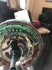
I assume I have to remove a little of the green top layer to bridge A gap in the track ?
Will the top layer come away without damaging the lower circuit ? If so what’s best way to remove top layer ?
Can you beep test tracks ? What’s best way ?
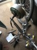
Can I test the motor out of the wheel ? I’m assuming you can and the cogs will just turn
I assume I have to remove a little of the green top layer to bridge A gap in the track ?
Will the top layer come away without damaging the lower circuit ? If so what’s best way to remove top layer ?
Can you beep test tracks ? What’s best way ?
Can I test the motor out of the wheel ? I’m assuming you can and the cogs will just turn
Last edited:
In readiness for doing track repair can I ask..
I assume I have to remove a little of the green top layer to bridge A gap in the track ?
Will the top layer come away without damaging the lower circuit ? If so what’s best way to remove top layer ?
Can you beep test tracks ? What’s best way ?
Can I test the motor out of the wheel ? I’m assuming you can and the cogs will just turn
I would not test the motor out of the wheel. It's likely to spin the cable into knots and cause damage. If you don't want to put the motor on the bike to test, make a test stand for the wheel out of MDF sheet or plywood.
Where there is a break in a track, go either side of the break and scrape off a couple of mm of the green insulation left on the good track either side of the break using a penknife. All it needs is a gentle scrape and it will come off and leave the copper underneath exposed. Scrape in the direction from the good side of the track towards the break, so you don't risk peeling off more good track.
If the break is small, say about 1 mm or less, you should be able to bridge it with a blob of solder. Otherwise, you will need to get a little bit of copper wire and solder it across the break. Do the beep test from either end of the good track, to test the bridge. If you are worried about insulating it again, you can coat the bridge with a bit of epoxy glue.
thanks . I guess use Plastic noT metal to scrape to avoid more damage . Only epoxy glue? No other glues or nail varnish ? I dint know whsts conductive or non conductiveI would not test the motor out of the wheel. It's likely to spin the cable into knots and cause damage. If you don't want to put the motor on the bike to test, make a test stand for the wheel out of MDF sheet or plywood.
Where there is a break in a track, go either side of the break and scrape off a couple of mm of the green insulation left on the good track either side of the break using a penknife. All it needs is a gentle scrape and it will come off and leave the copper underneath exposed. Scrape in the direction from the good side of the track towards the break, so you don't risk peeling off more good track.
If the break is small, say about 1 mm or less, you should be able to bridge it with a blob of solder. Otherwise, you will need to get a little bit of copper wire and solder it across the break. Do the beep test from either end of the good track, to test the bridge. If you are worried about insulating it again, you can coat the bridge with a bit of epoxy glue.
I use a metal blade, just be careful with it. Nail varnish is probably fine. Other glues may be ok, but they need to be reasonably heat resistant as it does get warm inside the motor.thanks . I guess use Plastic noT metal to scrape to avoid more damage . Only epoxy glue? No other glues or nail varnish ? I dint know whsts conductive or non conductive
I don't mind helping if the poster listens and tries. if they start being rude/offensive then I don't bother. I think Mike's one fixation is about the R2 which might be a red herring as it appears to be linked to the speed sensor track for which there isn't a senor fitted.
And it begs the question about how it blew when only one end is connected.I don't mind helping if the poster listens and tries. if they start being rude/offensive then I don't bother. I think Mike's one fixation is about the R2 which might be a red herring as it appears to be linked to the speed sensor track for which there isn't a senor fitted.
Good news and bad news .I use a metal blade, just be careful with it. Nail varnish is probably fine. Other glues may be ok, but they need to be reasonably heat resistant as it does get warm inside the motor.
Good ... When I gently scraped at the alleged damaged tracks they are Ok And it’s only rubbish from the untidy soldering That made tracks look damaged
Bad .... the motor doesn’t run with halls disconnected . But are you sure about that if somebody else set it up ?
I am left with only 2 other known possibilities and after that it’s for sale for repair or spares unless you’ve any other thoughts
1. The motor may not run with halls disconnected .
2. R2 which you think does nothing may do something. And the guy replaced what was on there only guessing , and ended up putting a 100nF capacitor when maybe it should be a resistor. ???
Attachments
-
 1.1 MB Views: 4
 -
 1.5 MB Views: 4
 -
 1.3 MB Views: 4
Good news and bad news .
Good ... When I gently scraped at the alleged damaged tracks they are Ok And it’s only rubbish from the untidy soldering That made tracks look damaged
Bad .... the motor doesn’t run with halls disconnected . But are you sure about that if somebody else set it up ?
I am left with only 2 other known possibilities and after that it’s for sale for repair or spares unless you’ve any other thoughts
1. The motor may not run with halls disconnected .
2. R2 which you think does nothing may do something. And the guy replaced what was on there only guessing , and ended up putting a 100nF capacitor when maybe it should be a resistor. ??
Attachments
-
 1.1 MB Views: 0
 -
 1.5 MB Views: 0
 -
 1.3 MB Views: 0
Where’s the bad attitude why are so interested To get these kind guys off the caseI dont get why people are still trying to help this guy, his attitude stinks.
One end of what please ?And it begs the question about how it blew when only one end is connected.
Wish one of you guys was bit closer. I’m sure you’d find out quickly what was wrong if you had it in Front of you
What vfr means is that it is strange that R2 "blew" when it seems as if nothing is connected to it.One end of what please ?
R2 One end is connected to ground and the other to the empty pad H, so there's no way for electricity to go through it. Pad H is to connect the speed sensor, but the holes where the speed sensor would be fitted are empty too, and no speed sensor has ever been fitted. It's an optional part.One end of what please ?
Good news and bad news .
Good ... When I gently scraped at the alleged damaged tracks they are Ok And it’s only rubbish from the untidy soldering That made tracks look damaged
Bad .... the motor doesn’t run with halls disconnected . But are you sure about that if somebody else set it up ?
I am left with only 2 other known possibilities and after that it’s for sale for repair or spares unless you’ve any other thoughts
1. The motor may not run with halls disconnected .
2. R2 which you think does nothing may do something. And the guy replaced what was on there only guessing , and ended up putting a 100nF capacitor when maybe it should be a resistor. ??
There are several possibilities.
1) the controller is set up so it has to have Hall sensors connected. But I think this is unlikely as it is a dual mode controller.
2) the controller is not switching on, or it is not giving an output for some reason.
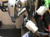
3) there is actually a break somewhere in the main wiring to the motor windings. Looking at your photos, it's hard to see that you have done the continuity test all the way from the 3 controller power cables to the motor windings, the insulation at those points looks intact.
Debugging this sort of thing is very frustrating process, hang on in there
")
GotchaR2 One end is connected to ground and the other to the empty pad H, so there's no way for electricity to go through it. Pad H is to connect the speed sensor, but the holes where the speed sensor would be fitted are empty too, and no speed sensor has ever been fitted. It's an optional part.
Probably didn’t . I’m quoting the solder guyWhat vfr means is that it is strange that R2 "blew" when it seems as if nothing is connected to it.
1. Well I’ve got the new sensors so I might as well try them . Though I think it will be a pig of job to remove old ones .There are several possibilities.
1) the controller is set up so it has to have Hall sensors connected. But I think this is unlikely as it is a dual mode controller.
2) the controller is not switching on, or it is not giving an output for some reason.
3) there is actually a break somewhere in the main wiring to the motor windings. Looking at your photos, it's hard to see that you have done the continuity test all the way from the 3 controller power cables to the motor windings, the insulation at those points looks intact.
Debugging this sort of thing is very frustrating process, hang on in there
2. The power / battery switch turns on Does that mean controller ok ?
3. I was advised to do continuity test from controller to solder points which I’ve done. And the thicker wires I was advised to do all at the controller end which I must admit confused me . So the 3 thick wires for where to where please
1. Well I’ve got the new sensors so I might as well try them . Though I think it will be a pig of job to remove old ones .
2. The power / battery switch turns on Does that mean controller ok ?
3. I was advised to do continuity test from controller to solder points which I’ve done. And the thicker wires I was advised to do all at the controller end which I must admit confused me . So the 3 thick wires for where to where please
The switch on the battery will just feed power to the controller. Isn't there a throttle with a switch on it? Like this:
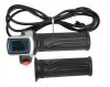
One way to tell if the controller is switched on is to see if you have power (ie 36V) on the lamp power out cable (no. 1):
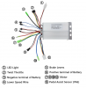
It is very important you check continuity of the fat cables from the controller to inside the hub. These are the most critical wires.
Related Articles
-
 MTF Enterprises announces acquisition of EMU Electric Bikes
- Started by: Pedelecs
-
 Wisper 806T folding bike wins Which? ‘Best Buy’
- Started by: Pedelecs
-
 Sustrans calls for protected cycle lanes
- Started by: Pedelecs
-
 Amazon launch their first UK e-cargo micromobility hub
- Started by: Pedelecs
