Brake sensor constantly on

Chris Maluszynski

Pedelecer
Jan 26, 2015
196
1
49
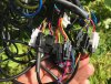
I just installed a new kit, but the display shows the brake sensor symbol and the bike won't run.
I suspect it's my fault as it seemed it all worked fine before I sprayed som WD40 on the brake cables.
Does anyone know how these brake sensors work? Could the WD40 be the culprit?
 
Last edited:

Nealh

Esteemed Pedelecer
Aug 7, 2014
19,990
8,173
60
West Sx RH
Disconnect one at a time to see if that clears the fault, ensure the lever fully seats when released.
Only one cut off is needed, two can add up to be double trouble.

A simple Reed switch (2 wires) will be used to activate the cut off signal, this is activated by a magnet manoeuvred inside a small enclosure with in the lever. When braking there is a small pressure button on the end of the enclosure pushed in/release by the cam action inside the lever.

WD40 may have found it's way in to the enclosure and affected the wiring, in affect causing a continuation short between the wire contacts or switch
 
Last edited:

vfr400

Esteemed Pedelecer
Jun 12, 2011
9,822
3,985
Basildon
the switch is a simple push-to-break switch. It's held off by the brake lever pushing against it when the lever is in its normal position. When you pull the lever, it moves away and allows the switch to go on. The power is switched off when the switch is on (high signal wire is connected to ground, which causes the signal to go low).

If it doesn't switch off, the lever isn't going all the way back, the cable is shorted, the connector is in the incorrect sequence (not signal to signal and ground to ground) or the switch is faulty.
 

Chris Maluszynski

Pedelecer
Jan 26, 2015
196
1
49
Ok, now I'm no longer suspecting the brake levers.
I unplugged everything and plugged it back in. The brake symbol on the LCD stays lit even when I disconnect the brakes.
The thing is I once had it working last night (even after the WD40) so this suggests something else is wrong. Could there be something wrong with the programming of the LCD? It's a KT-LCD5 and the controller is from PSW Power KT36/48SVPR-17A
 

vfr400

Esteemed Pedelecer
Jun 12, 2011
9,822
3,985
Basildon
The connector on the controller must be shorted or the cable between there and the PCB. Follow it all the way to the PCB to find where the problem is.

The signal is held at 5v by a pull-up resistor on the PCB. The only way it can signal the brake on is if one of those two signal wires is shorted to ground somewhere.

Show us a photo of the connectors you have and what's connected. Are you sure that you haven't got your connectors mixed up as to which is which?
 

Chris Maluszynski

Pedelecer
Jan 26, 2015
196
1
49
So I should open up the controller enclosure to check for shorts? The cables outside the box seem fine.
Here's a photo of the connections. Hopefully decipherable.31388
 

Nealh

Esteemed Pedelecer
Aug 7, 2014
19,990
8,173
60
West Sx RH
Brakes are the pair of Blue/Red that connect to the Red /Black/Yellow.
Blue to Black is Gnd and Red to Yellow is signal.
Disconnect the pair and check each connector/pins are ok, stick your meter probes in to the rear of each wire connector and probe the opposing wires to ensure good connection/continuity ( set the meter to buzz mode if it has one).
If you open the controller trace the Yellow to the board ( wiring can be tight so be careful) it may even be a bad solder connection, it's not impossible that the Yellow is soldered to ground but should think unlikely. If you remove top two end screws the lid will pry off.
The Yellow signal is soldered to S1 on the board which is next the ground take off (front RHS where the wire bundle enters), you would need to slide the pcb out to check the rear soldering track isn't bad/ or shorted. For this you have to remove the screws on the side that hold the mosfets reatiners and remove the two other end screws where wires enter to slide the board out.
 
Last edited:

Chris Maluszynski

Pedelecer
Jan 26, 2015
196
1
49
The mystery tightens.
I opned up the box. All connections and cables inside look ok.
But here comes the really weird part:
I measured voltage between the signal (yellow) and black (Gnd) on both brake connectors coming from the controller while the power is on.
On one of them voltage is 0. But on the other it's 0.70V !! How is this possible? They both connect to the same place.
I'm guessing this is the problem. But how?? And what do I do about it?
 

vfr400

Esteemed Pedelecer
Jun 12, 2011
9,822
3,985
Basildon
The yellow wire should be 5V, but it gets that through a pull-up resistor, so if you draw any current, the voltage will collapse. Try a different meter with a higher impedence.
 

Chris Maluszynski

Pedelecer
Jan 26, 2015
196
1
49
The yellow wire should be 5V, but it gets that through a pull-up resistor, so if you draw any current, the voltage will collapse. Try a different meter with a higher impedence.
Oh, there should be 5v between the black and the yellow? And the fault is in my meter? Not sure I can get a different meter very easily. Is there anything else at all that could be causing the problem?

The brake levers are working fine by the way, I checked with my meter.
 

Chris Maluszynski

Pedelecer
Jan 26, 2015
196
1
49
My meter is digital. So if I understand this correctly there is next to no voltage where there should be 5V. But how is it possible that the voltage is different between the two connectors when they all connect to the same place? And what could be causing it to have no voltage?
 

TJS109

Pedelecer
Sep 29, 2017
112
48
76
Glos
The voltage cannot be different if they are connected by a low impedance i.e. the same place so :-
Are you using the same reference point when measuring the voltages?
Try disconnecting the power and use your meter to measure the resistance between the points you think are the same. if they are you should get a very low reading if you dont then they are not directly connected.

the problem seems to indicate a short of some kind doesn't have to be to ground two signal wires could be connected. The other possibility of course is a controller failure.
 

Chris Maluszynski

Pedelecer
Jan 26, 2015
196
1
49
I measured again, and finallly got the same reading on both sensors. So that's out of the way. But still only 0.7V instead of 5
 

TJS109

Pedelecer
Sep 29, 2017
112
48
76
Glos
Well that's sort of better. 0.7 volts indicates a diode drop so could be connected to another output on the controller. Have you disconnected all the connectors to the brakes ? if so try disconnecting other wiring
and see if anything changes
 

Chris Maluszynski

Pedelecer
Jan 26, 2015
196
1
49
Disconnected everything one at a time (and multiple things), everything except the hall sensors coming from the wheel (I suspect these could not cause trouble?). And unfortunately no luck. Keep getting 0.7V. Is the controller faulty?
 

Chris Maluszynski

Pedelecer
Jan 26, 2015
196
1
49
One time tonight the brake light came off for two consecutive power ons, and the bike was working. But now it's back on again, and looks intent on staying. (I did not touch the brakes) Seems like voodoo to me.
 
Last edited:

Nealh

Esteemed Pedelecer
Aug 7, 2014
19,990
8,173
60
West Sx RH
Turn the bike off disconnect both brakes and switch in does every thing work ?
Kit should work with no brakes connected.
Double check motor wire connector is correctly aligned and connected.