Most likely issue is that one of the phase mosfets has fried, rather then use one of those stupid light gadgets it will be much easier to understand with proper resistance values by using a Digital volt meter.
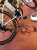
Simply disconnect the controller (no power) , attach the probes to Red battery input wire and each of the phases in turn using the 20k or 200k positions on the dial. Write down and show us the results, also do the same for the Black battery in put wire.
One should get two sets of results (each set may be different) , but if any result in each pair of results is massively different then a mosfet has fried.
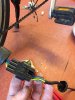
Going by the light thingy the green mosfet should show up a different result.
Simply disconnect the controller (no power) , attach the probes to Red battery input wire and each of the phases in turn using the 20k or 200k positions on the dial. Write down and show us the results, also do the same for the Black battery in put wire.
One should get two sets of results (each set may be different) , but if any result in each pair of results is massively different then a mosfet has fried.
Going by the light thingy the green mosfet should show up a different result.
Last edited: