
That is very clever, I knew there was some sort of freewheel in there somewhere, but I didn't expect this. It's amazing they are as reliable as they are.z0mb13e, the pedal force drive into the pedal shaft is transferred into the inboard end of the surrounding amorphous sleeve, and from the r/h outboard end of that sleeve the drive goes into a pawl freewheel that connects to the independent chainring and thence to the chain. Therefore all the pedal force runs though the sleeve which is turning at the same rate and in the same direction as the pedalshaft. The photo below shows the inboard inner splines on the shaft which transfers drive into the sleeve, and the outboard outer splines that connect the sleeve into the pawl freewheel for the r/h chainring. The chainring has to be freewheeled so that any slight motor overrun when pedalling stops does not kick the pedals from the rider's feet. Here the amorphous sleeve is within it's readout coil unit below the pedalshaft:

Looking at at the voltages you measured on the sensor connector I think you are right, it is most likely phase displacement.I don't really think of it as a differential transformer -- more a bridge type circuit with unbalance caused by differing inductance of the two coils as the susceptibility of the magnetic core changes as a result of the torque.
Were these voltages measured with a meter or the scope? I'm wondering if you have seen that 17kHz waveform here other than just picking it up as interference.
Torque sensor socket:
5.01 V
6.23 V
6.23 V
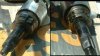
The components are very substantial, really chunky double width pawls and engagement teeth, automotive precision sealed bearings rather than the cheap ballraces so often used in bikes, and the pedal shaft has to be handled to appreciate the engineering quality and how strong it is. For example, below is the chunky pawl assembly of that chainwheel freewheel, the same double tooth pawl the opposite side, and alongside a two-angle view of the toothed housing it sits in, complete with it's sealed external bearing. Internally that housing has a needle roller race for the freewheeling function. The end splines carry the chainring and it's circlip:That is very clever, I knew there was some sort of freewheel in there somewhere, but I didn't expect this. It's amazing they are as reliable as they are.


Last edited:
Pawl Flipped & Amorphous metal?
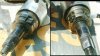
When I withdrew this chain ring shaft today I found that one the two pawls was installed flipped over. the one in the left pic below is correct. The right pic showing the pawl on the opposite side shows that pawl flipped to be over, so it would not engage. Has this bike been running with only one pawl engaging, or did the flip over happen when Cyclezee opened the motor to see what was wrong? If he did not withdraw this shaft from the housing then I cant see how his opening up could have caused the flip over.

I don't think that this was the problem causing the motor to fail since Cyclezee reported torque sensor zeroing error lights, and I don't see how a flip over of one pawl would cause that. When one switches on one is supposed not to pedal while the zeroing takes place. I imagine that zeroing is just the balancing by means of the bridge of the inductance on the two sensor coils with no twist in the torque shaft.
Another question, for Flecc: You refer to the surface metalisation/sleeve of the torque sensor as being amorphous. This means having no significant size of crystals in metal. How do you know it is amorphous? I thought that amorphous structures were normally obtained in things like a thin film coating. The patterned sleeve on the outside of the torque cylinder has visible thickness, and I assume strength. I wonder whether it would exhibit useful magnetic properties, if it had no crystalline structure.
This is something I was intending to ask about, but had not got around to it in my earlier post today..........For example, below is the chunky pawl assembly of that chainwheel freewheel, the same double tooth pawl the opposite side, ......
When I withdrew this chain ring shaft today I found that one the two pawls was installed flipped over. the one in the left pic below is correct. The right pic showing the pawl on the opposite side shows that pawl flipped to be over, so it would not engage. Has this bike been running with only one pawl engaging, or did the flip over happen when Cyclezee opened the motor to see what was wrong? If he did not withdraw this shaft from the housing then I cant see how his opening up could have caused the flip over.
I don't think that this was the problem causing the motor to fail since Cyclezee reported torque sensor zeroing error lights, and I don't see how a flip over of one pawl would cause that. When one switches on one is supposed not to pedal while the zeroing takes place. I imagine that zeroing is just the balancing by means of the bridge of the inductance on the two sensor coils with no twist in the torque shaft.
Another question, for Flecc: You refer to the surface metalisation/sleeve of the torque sensor as being amorphous. This means having no significant size of crystals in metal. How do you know it is amorphous? I thought that amorphous structures were normally obtained in things like a thin film coating. The patterned sleeve on the outside of the torque cylinder has visible thickness, and I assume strength. I wonder whether it would exhibit useful magnetic properties, if it had no crystalline structure.
Attachments
-
 27.3 KB Views: 8
 -
 28.2 KB Views: 60
C
Cyclezee
Guest
Mike,This is something I was intending to ask about, but had not got around to it in my earlier post today..
When I withdrew this chain ring shaft today I found that one the two pawls was installed flipped over. the one in the left pic below is correct. The right pic showing the pawl on the opposite side shows that pawl flipped to be over, so it would not engage. Has this bike been running with only one pawl engaging, or did the flip over happen when Cyclezee opened the motor to see what was wrong? If he did not withdraw this shaft from the housing then I cant see how his opening up could have caused the flip over.
I don't think that this was the problem causing the motor to fail since Cyclezee reported torque sensor zeroing error lights, and I don't see how a flip over of one pawl would cause that. When one switches on one is supposed not to pedal while the zeroing takes place. I imagine that zeroing is just the balancing by means of the bridge of the inductance on the two sensor coils with no twist in the torque shaft.
Just to clarify, I did not open the motor casing until after the fault occured and I did not withdraw the chain ring shaft. I only gave the internals a cursory glance looking for an obvious fault such as a broken or loose wire which I didn't really expect to find. Then I put the casing back together.
Mike,
Just to clarify, I did not open the motor casing until after the fault occured and I did not withdraw the chain ring shaft. I only gave the internals a cursory glance looking for an obvious fault such as a broken or loose wire which I didn't really expect to find. Then I put the casing back together.
Thanks for confirming this. I am certain I did not flip the pawl over when I was dismantling, since it is firmly held by the retaining spring. I had to lever the spring with a screw driver to be able to flip the pawl back to the correct position. It seems to be so well secured that I can't really imagine that it could have become flipped during the operation of your bike - even over the 10,000 miles it has done in 3.5 years. So did it just land up in this position as an assembly error? If so, then the other, correctly oriented, pawl must have done the job of protecting the pedals from the turning force of any motor over-run.
Although this pawl is located on the torque sensor shaft I can't see that it would have given rise to the torque sensor fault error code that you got when this motor died.
That pawl assembly error could well be the problem 10mph.
Panasonic have at one time used the amorphous alloy sleeve description and I have seen 50cycles repeat it in a post in here. Since Panasonic understandably release so little information about units not designed for internal repairs, this is how I gained my knowledge of them over time, from little snippets that escape into the wild which I piece together.
Panasonic have at one time used the amorphous alloy sleeve description and I have seen 50cycles repeat it in a post in here. Since Panasonic understandably release so little information about units not designed for internal repairs, this is how I gained my knowledge of them over time, from little snippets that escape into the wild which I piece together.
Torque sensor using amorphous magnetostrictive ribbons
My solid state physics text books were written in the 1950s. Since 1963 I have only sought information about solid state physics and magnetism on a "need to know basis". I now discover by referring to Wikipedia that in 1960 "the first reported metallic glass was an alloy (Au75Si25) produced at Caltech by W. Klement (Jr.), Willens and Duwez."
Until know I have never needed to know about metallic glasses or "amorphous metal" as the Wikipedia article is titled.
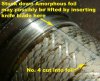
I had another even closer look at the torque sensor and I now see that in my original inspection I had failed to rotate it through 360 degrees or I would have seen this narrow gap:

I had wondered how such a thin sleeve could have been assembled over the torque sensor shaft. Now we can see that is made from a rectangular piece of foil carefully stuck on. Perhaps the purpose of the turning grooves on the shaft is to hold the glue.
It is not obvious exactly what is the significance of the number 4 cut into the foil. Perhaps Panasonic use different foils for different motors.
So next I did some more googling and came up with this conference abstract:
Materials Science and Engineering: A
Volumes 181-182, 15 May 1994, Pages 1378-1382
Proceedings of the Eighth International Conference on Rapidly Quenched and Metastable Materials: Part 2
Torque sensor using amorphous magnetostrictive ribbons

by Hiroyuki Hase, Rihito Shoji and Masayuki Wakamiya
Materials and Devices Research Laboratory, Matsushita Electric Industrial Co. Ltd., 1006, Kadoma, Kadoma-shi, Osaka 571, Japan
Abstract
A torque sensor using amorphous magnetostrictive ribbons was developed. An inaccuracy of less than 1% in the temperature range − 10 to 50 °C was achieved by controlling the bias compressive stress of glued amorphous ribbons, which is induced by the difference between the thermal expansion of the shaft and the glued amorphous ribbons during the glueing process. In this kind of torque sensor, a rotation magnetization model can be used to explain the sensor output characteristics when the compressive bias stress is relatively large.
I suspect that just reading the above abstract provides all we Panasonic Motor Users need to know about this technology.
Your knowledge never ceases to amaze!That pawl assembly error could well be the problem 10mph.
Panasonic have at one time used the amorphous alloy sleeve description and I have seen 50cycles repeat it in a post in here. Since Panasonic understandably release so little information about units not designed for internal repairs, this is how I gained my knowledge of them over time, from little snippets that escape into the wild which I piece together.
My solid state physics text books were written in the 1950s. Since 1963 I have only sought information about solid state physics and magnetism on a "need to know basis". I now discover by referring to Wikipedia that in 1960 "the first reported metallic glass was an alloy (Au75Si25) produced at Caltech by W. Klement (Jr.), Willens and Duwez."
Until know I have never needed to know about metallic glasses or "amorphous metal" as the Wikipedia article is titled.
I had another even closer look at the torque sensor and I now see that in my original inspection I had failed to rotate it through 360 degrees or I would have seen this narrow gap:
I had wondered how such a thin sleeve could have been assembled over the torque sensor shaft. Now we can see that is made from a rectangular piece of foil carefully stuck on. Perhaps the purpose of the turning grooves on the shaft is to hold the glue.
It is not obvious exactly what is the significance of the number 4 cut into the foil. Perhaps Panasonic use different foils for different motors.
So next I did some more googling and came up with this conference abstract:
Materials Science and Engineering: A
Volumes 181-182, 15 May 1994, Pages 1378-1382
Proceedings of the Eighth International Conference on Rapidly Quenched and Metastable Materials: Part 2
Torque sensor using amorphous magnetostrictive ribbons
by Hiroyuki Hase, Rihito Shoji and Masayuki Wakamiya
Materials and Devices Research Laboratory, Matsushita Electric Industrial Co. Ltd., 1006, Kadoma, Kadoma-shi, Osaka 571, Japan
Abstract
A torque sensor using amorphous magnetostrictive ribbons was developed. An inaccuracy of less than 1% in the temperature range − 10 to 50 °C was achieved by controlling the bias compressive stress of glued amorphous ribbons, which is induced by the difference between the thermal expansion of the shaft and the glued amorphous ribbons during the glueing process. In this kind of torque sensor, a rotation magnetization model can be used to explain the sensor output characteristics when the compressive bias stress is relatively large.
I suspect that just reading the above abstract provides all we Panasonic Motor Users need to know about this technology.
Attachments
-
 47.8 KB Views: 42
That's an excellent bit of research you've done there 10mph and I'm sure you are right on this. It really is all we need to know about the torque sensor and it's action.I suspect that just reading the above abstract provides all we Panasonic Motor Users need to know about this technology.
C
Cyclezee
Guest
I have a few questions.That pawl assembly error could well be the problem 10mph.
Tony and Mike,
- Could such an error pass undetected through what I would imagine to be quite stringent QC checks by Panasonic?
- If it was an assembly error, would the individual owner know there was a problem and how would it manifest itself in the riding experience? I have owned and ridden several Panasonic powered bikes and not noticed and perceptible differences between this and the others.
- How does this issue relate to the error message at the control switch, or is it not related?
Last edited by a moderator:
Good questions.
1. If pawl was flipped on assembly then QC failed. The best QA does fail eg Shuttle 'O' rings.
2. Not sure, it would seem that just one pawl would do the job. May be a slight bending force on the torque shaft during motor overrun. I don't think the flipped pawl interferes with anything.
3. I can't see how it would cause the error message. My interpretation of the torque sensor calibration, is that when the pedals are not turning there is no torque on the shaft, and the electronics calibrate itself by recognising this zero torque signal. It then measures actual pedal torque relative to this condition using some built in and fixed calibration factor.
Thanks very much for the generous offer of more help. I won't take you up on it just yet since there is more to be got out of my present investigations. I have been investigating the connections on my Kalkhoff, without touching the motor. When my bike was up on my new bike stand yesterday I took off all the plastic parts and could see much more of the wiring. Maybe tomorrow I will write up a post with pictures of what I have seen. I have a half formed plan of how to work out the control wires.
Similar to 10mph's reply. With the much larger scale of production of these units now, plus the fact they are produced in variants which will take up attention to ensuring that goes right, simple issues like the faulty pawl assembly could easily be overlooked by QC in concentrating on the more complex.
I think it's possible the one sided pawl could cause an unbalance in the torque readings. The outer cup of the pawl assembly freewheels on a needle roller set and there is some tolerance which could allow it to tilt under one sided engagement. In turn this could result in a tilt in the pressures from the pawl inner block which engages the end or the amorphous alloy sleeve. Given the tiny signals the sensing operates with, there could be an effect.
However, as Mike said, this could not produce the error message so the unit does have a specific fault in addition to that assembly error. Maybe what's known in the business as a Monday morning or Friday afternoon one.
C
Cyclezee
Guest
From Japan? I thought that was only an issue with British manufacturingMaybe what's known in the business as a Monday morning or Friday afternoon one.
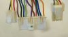
But then of course there is ToyotaI wonder whether any forum member can guide me towards a source of this 11 pin plug used on the Panasonic motor and its matching socket attached to the cable leading to the handlebar unit?

Here is a picture of the plug mated with a socket - taken from my 2011 model Agattu. It seems to be the same wiring.

I have also emailed 50 cycles for help with understanding the connections to the handlebar unit, and I have asked whether they can sell me either the old style or the new style handle bar unit.
Here is a picture of the plug mated with a socket - taken from my 2011 model Agattu. It seems to be the same wiring.
I have also emailed 50 cycles for help with understanding the connections to the handlebar unit, and I have asked whether they can sell me either the old style or the new style handle bar unit.
Attachments
-
 14.6 KB Views: 61
 -
 16.9 KB Views: 61
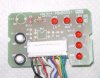
Photo of handlebar unit(old style) agattu SW3 is power SW2 mode
Attachments
-
 85.2 KB Views: 20
Last edited:
Can we see the 11pin connector end on?I wonder whether any forum member can guide me towards a source of this 11 pin plug used on the Panasonic motor and its matching socket attached to the cable leading to the handlebar unit?
Here is a picture of the plug mated with a socket - taken from my 2011 model Agattu. It seems to be the same wiring.
I have also emailed 50 cycles for help with understanding the connections to the handlebar unit, and I have asked whether they can sell me either the old style or the new style handle bar unit.
That is brilliant. You are a star des56daw!Photo of handlebar unit(old style) agattu SW3 is power SW2 mode
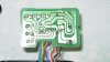
Seeing the component on this side of the board may be enough to work out what is going on.
Any chance of a pic showing the PCB pattern on the other side of the board?
I appreciate your help.Can we see the 11pin connector end on?
I have only been able to get a photo of the socket end of the 11 pin connector from the dud motor. I would have to put my working bike up on the stand and dismantle to break the connector to get a view of the 11 pin plug end. I am reluctant to do this unless you definitely need a view of the pins to aid identification.
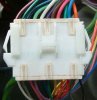
I have also photo'd the pins on a similar socket - the 6 pin Hall socket on the circuit board and the 3 pin torque sensor socket. I assume that the pins of the 11 pin plug must be similar. Included in this picture is the region of the board with the input circuits to process these signals. I can't make really make anything from what I see on this side of the board. The processor is to the left.
Attachments
-
 19.7 KB Views: 41
 -
 91.9 KB Views: 89
No need to take apart the working bike...I appreciate your help.
I have only been able to get a photo of the socket end of the 11 pin connector from the dud motor. I would have to put my working bike up on the stand and dismantle to break the connector to get a view of the 11 pin plug end. I am reluctant to do this unless you definitely need a view of the pins to aid identification.
It looks like a 0.1" pitch molex type connection, though the 3 locking ramps are not standard. If the pitch is 0.1" then this might do the trick.
The two other connections are slightly different, but again, 0.1" pitch molex connectors would probably fit the header on the PCB. Without a Molex or Foxconn catalog it would be difficult to track down the exact connector as there are so many of them.I have also photo'd the pins on a similar socket - the 6 pin Hall socket on the circuit board and the 3 pin torque sensor socket. I assume that the pins of the 11 pin plug must be similar. Included in this picture is the region of the board with the input circuits to process these signals. I can't make really make anything from what I see on this side of the board. The processor is to the left.

Related Articles
-
 MTF Enterprises announces acquisition of EMU Electric Bikes
- Started by: Pedelecs
-
 Wisper 806T folding bike wins Which? ‘Best Buy’
- Started by: Pedelecs
-
 Sustrans calls for protected cycle lanes
- Started by: Pedelecs
-
 Amazon launch their first UK e-cargo micromobility hub
- Started by: Pedelecs
