
No, they sit alongside the motor on a sub-board, here's the sub-board on the circular outboard crankcase wall against which the motor bolts:

Below is the older unit where the Hall sensor board mounted directly on the motor wall making assembly difficult, hence the mounting change, otherwise the same thing though:

Below is the older unit where the Hall sensor board mounted directly on the motor wall making assembly difficult, hence the mounting change, otherwise the same thing though:
I've been reading up on how to control brushless motors with microcontrollers and it would be interesting to know what the outlying chips are to get a better picture of how much is handled directly by the µC.
I've only ever used controller chips to control brushless motors, so have never really looked at the theory, but controlling the motor directly does give you a lot of control and I can see why there is room to tweak things. It could, in theory, be possible to add throttle only mode or perhaps a throttle that controls the amount of effort rather than based on the torque sense and maybe a low speed high torque mode for hill climbing (if it doesn't do that already). It would likely cut the range drastically though.
I can only guess at what sort of information is generated by the torque sensor. Perhaps if I have time I will read up on that.
This evening I set up the motor and instrumentation again on the kitchen table. I having to share my use of the kitchen as an electronics lab with its more normal culinary functions. Unfortunately my work bench in the garage is not really suitable for this delicate work on the controller board.
This time I plugged in the lead to the torque sensor, after Flecc reminded me earlier today that the first function on switching on is to "calibrate" the torque sensor. This made no perceptible difference.
Again I probed the handlebar cable connector hoping to see some fluctuations with a second or so interval as signals went out to flash the handlebar LEDs in order to indicate a fault condition. The reader may remember that originally when the motor failed Cyclezee reported that the power LEDs and then the mode LEDs flashed alternately which indicated a zero setting error on the torque sensor. All pins were steady at earth potential except for one steady at over 20V. If the unit is functioning correctly then that pin would be the medium mode LED, but I would also expect a battery level LED to be on. However I cant be sure how the LEDs are connected in the handlebar unit - perhaps they could all be commoned to the 20+V line and switched on the negative side.
So, in summary, I don't know from the tests so far whether I am reproducing the fault condition discovered by Cyclezee.
Next I fired up the oscilloscope and probed around. I had cleaned off the potting from the test connection location beside the Hall connector, but these points proved to have rather uninteresting 0V or +5V. However, I immediately picked up a 17kHz square wave just by approaching the circuit board with the probe. This turned out to be very strong when the probe was placed adjacent to the cable going to the torque sensor. Perhaps it is a waveform to excite the sensor bridge coils which flecc described earlier today. Like z0mb13e I have not read up on how a magnetic torque sensor works. The descriptions I have read have a piezoelectric or resistance type of sensor. I suppose that the magnetic coupling is necessary here to connect to sense the strain in the rotating pedal drive to the chain wheel.
I am not sure where I go next.
Cyclezee, do you still have the handlebar unit from the scrap bike from which you took the replacement motor now installed in your son's bike?
Well done,it all sounds very impressive so far, even if I have to admit I have absolutely no comprehension of what you are all talking about...... but, one thing for certain....... sure knows how to keep grown men happy and occupied ")
Lynda
Lynda
C
Cyclezee
Guest
Sorry Mike, the only parts I obtained from the scrapped bike were the frame and motor.Cyclezee, do you still have the handlebar unit from the scrap bike from which you took the replacement motor now installed in your son's bike?
As I suggested earlier in this thread, it may be worth approaching a Panasonic dealer, e.g. 50cycles or Onbike to see if they would donate a handlebar control unit. They would no doubt be interested in the results of your research. Very impressive to date.
Last edited by a moderator:
C
Cyclezee
Guest
Hey Funky, must work on my skills to keep ladies like yourself happy and occupiedWell done,it all sounds very impressive so far, even if I have to admit I have absolutely no comprehension of what you are all talking about...... but, one thing for certain....... sure knows how to keep grown men happy and occupied
Lynda
Any suggestions welcomeOh ...........what a shame..........if only you had said you needed help I would have stopped off on my way past MK last monday........but perhaps you could make a start without me by trying to curb your obsession with weird metal bits ???? ( unless painted red )Hey Funky, must work on my skills to keep ladies like yourself happy and occupied
Funky
C
Cyclezee
Guest
Dear Funky,
I think it might be time to take our relationship somewhere else before we start upsetting the nice people who just want to read a serious technical thread like this
Yours or mine
I think it might be time to take our relationship somewhere else before we start upsetting the nice people who just want to read a serious technical thread like this
Yours or mine
I don't suppose anyone here is a member of the IEEE?
Was trying to find out more about the torque sensor and found this paper on Magnetostrictive torque sensor and its output characteristics which sounds about right. You need a subscription to read the full article.
There are two possibilities for how this sensor works. In one case Both coils are excited and eddy currents are detected as a phase difference depending on the state of the core material or alternatively one coil is excited and a current induced in the other varies according to the state of the core material.
It may be possible to deduce the mode of operation by knowing more about the chips connected to (or near) the torque sensor connector.
Can I suggest that you fit a new standard 48 volt 12 mosfet controller only using the hall sensors and 3 power leads to the motor not the pedal sensor
and use a twist throttle so it will chuck out 500 watts with twist and GO
Speed approx 25/30 MPH
Frank
and use a twist throttle so it will chuck out 500 watts with twist and GO
Speed approx 25/30 MPH
Frank
This makes for interesting reading (you might have to rename the downloaded files file extension to pdf to make it work).I've always thought both will be excited with eddy current imbalance used to indicate the torque. From observation of the components I tend to doubt current generation in one coil half in response to torque forces would be possible to a usable extent.
It describes the 'Phase Displacement' torque sensor and the 'Differential Transformer' type.
It's difficult for me to be certain which type the Panasonic unit is using. The 'Phase Displacement' type is definitely a possibility given the pattern on the sleeve, though the fact that the coils are physically so close could suggest 'Differential Transformer'. I'm on the fence until I know more... given that yesterday I knew little to nothing about magnetic torque sensors!
It is the Villari effect
Or the inverse-magnetostrictive effect on which the torque sensor is based.
But first thanks to recent contributors, and to respond :
Cyclezee: Good point about approaching suppliers for a surplus handlebar unit. I will summon up some energy to write begging letter email to the companies you suggest.
Banbury Frank: That is a good idea to resurrect the motor itself with another controller, But I don't have a non-working bike adapted for chain drive to put it in, and I don't have equipment to fabricate a mounting arrangement for another bike. Anyway my aim is to understand how the Panasonic unit works and perhaps even locate the fault in this dud one.
Flecc: Thanks as ever for your pictures and info on your web pages. Following them I have just taken the torque sensor apart and taken a high resolution photo of the shaft which carries the torque from the pedals to the chain wheel. I can now see more than I can with my eyes or in your smaller photos. See below.
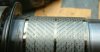
I agree the torque sensor is based on the the Villari effect (never heard of that name before!). See this close up:

In this close up picture I can see that shaft which carries the pedal torque to the chainwheel has fine circumferential grooves. Over the top of this shaft is fitted a gold coloured very thin metal sleeve with two areas of diagonal cutouts oriented at right angles. The two sensor coils (shown in Flecc's picture) fit over the top of these areas.
Now, I assume that the gold coloured metal is has a good Villari effect - it could well operate by changing its magnetic susceptibility when under strain. This will change the impedance of the sensing coil when excited with the 17kHz square wave which I observed to be present. Assuming the two coils are connected in a bridge circuit then the circuit impedance would become unbalanced if the two areas of gold coloured metal have different magnetic susceptibility
The diagonal cutouts on the gold coloured metal respond to the diagonal stresses due to the torque carried in the underlying metal shaft - I assume that the gold coloured metal is a very tight, shrink fit, to the underlying shaft. One are will have experience a higher susceptibility as the metal along the slots is stretched, the other area will experience a lower susceptibility as the metal is compressed in the perpendicular diagonal direction.
Note this type of torque sensor will not provide information on rotation rate or cadence. This information has to be provided to the controller from the motor rotation and the gearing.
Sorry for the long-winded explanation. It is difficult to edit to improve the writing in this tiny edit box!!!
Also, z0mb13e: I will soon strip the potting from the other circuits and see if i can find markings. I will also photo this area of the circuit in close up.
Or the inverse-magnetostrictive effect on which the torque sensor is based.
But first thanks to recent contributors, and to respond :
Cyclezee: Good point about approaching suppliers for a surplus handlebar unit. I will summon up some energy to write begging letter email to the companies you suggest.
Banbury Frank: That is a good idea to resurrect the motor itself with another controller, But I don't have a non-working bike adapted for chain drive to put it in, and I don't have equipment to fabricate a mounting arrangement for another bike. Anyway my aim is to understand how the Panasonic unit works and perhaps even locate the fault in this dud one.
Flecc: Thanks as ever for your pictures and info on your web pages. Following them I have just taken the torque sensor apart and taken a high resolution photo of the shaft which carries the torque from the pedals to the chain wheel. I can now see more than I can with my eyes or in your smaller photos. See below.
I never joined the IEEE - too much money for too little. Thanks for the links. The Journal of Physics paper, I can probably find and read for free in the the library of a nearby University for which I have a free old person's reader's card.I don't suppose anyone here is a member of the IEEE?
Was trying to find out more about the torque sensor and found this paper on Magnetostrictive torque sensor and its output characteristics which sounds about right. You need a subscription to read the full article.
There are two possibilities for how this sensor works. In one case Both coils are excited and eddy currents are detected as a phase difference depending on the state of the core material or alternatively one coil is excited and a current induced in the other varies according to the state of the core material.
It may be possible to deduce the mode of operation by knowing more about the chips connected to (or near) the torque sensor connector.
I agree the torque sensor is based on the the Villari effect (never heard of that name before!). See this close up:
In this close up picture I can see that shaft which carries the pedal torque to the chainwheel has fine circumferential grooves. Over the top of this shaft is fitted a gold coloured very thin metal sleeve with two areas of diagonal cutouts oriented at right angles. The two sensor coils (shown in Flecc's picture) fit over the top of these areas.
Now, I assume that the gold coloured metal is has a good Villari effect - it could well operate by changing its magnetic susceptibility when under strain. This will change the impedance of the sensing coil when excited with the 17kHz square wave which I observed to be present. Assuming the two coils are connected in a bridge circuit then the circuit impedance would become unbalanced if the two areas of gold coloured metal have different magnetic susceptibility
The diagonal cutouts on the gold coloured metal respond to the diagonal stresses due to the torque carried in the underlying metal shaft - I assume that the gold coloured metal is a very tight, shrink fit, to the underlying shaft. One are will have experience a higher susceptibility as the metal along the slots is stretched, the other area will experience a lower susceptibility as the metal is compressed in the perpendicular diagonal direction.
Note this type of torque sensor will not provide information on rotation rate or cadence. This information has to be provided to the controller from the motor rotation and the gearing.
Sorry for the long-winded explanation. It is difficult to edit to improve the writing in this tiny edit box!!!
Also, z0mb13e: I will soon strip the potting from the other circuits and see if i can find markings. I will also photo this area of the circuit in close up.
Attachments
-
 33.8 KB Views: 58
Last edited:
A to B magazine did this on an old failed unit Frank, describing it in the magazine some while ago, They continued to use the existing integrated 24 volt NiMh battery, stripped out all the surplus gubbins from the unit and mounted the new controller on the seat tube. Twistgrip controlled of course.Can I suggest that you fit a new standard 48 volt 12 mosfet controller only using the hall sensors and 3 power leads to the motor not the pedal sensor
I did briefly - I got a graduate rate membership for a year a long while back, but full membership dues are too steep for me.I never joined the IEEE - too much money for too little. Thanks for the links. The Journal of Physics paper, I can probably find and read for free in the the library of a nearby University for which I have a free old person's reader's card.
Count yourself lucky, that was a name I had long since forgotten. His name cropped up when learning about the detailed theory of electric motors. From what little I remember it was mind numbing stuff.I agree the torque sensor is based on the the Villari effect (never heard of that name before!).
I think you are right, that the sleeve is probably exaggerating the magnetic properties of the shaft.See this close up:
In this close up picture I can see that shaft which carries the pedal torque to the chainwheel has fine circumferential grooves. Over the top of this shaft is fitted a gold coloured very thin metal sleeve with two areas of diagonal cutouts oriented at right angles. The two sensor coils (shown in Flecc's picture) fit over the top of these areas.
Now, I assume that the gold coloured metal is has a good Villari effect - it could well operate by changing its magnetic susceptibility when under strain. This will change the impedance of the sensing coil when excited with the 17kHz square wave which I observed to be present. Assuming the two coils are connected in a bridge circuit then the circuit impedance would become unbalanced if the two areas of gold coloured metal have different magnetic susceptibility
The diagonal cutouts on the gold coloured metal respond to the diagonal stresses due to the torque carried in the underlying metal shaft - I assume that the gold coloured metal is a very tight, shrink fit, to the underlying shaft. One are will have experience a higher susceptibility as the metal along the slots is stretched, the other area will experience a lower susceptibility as the metal is compressed in the perpendicular diagonal direction.
Note this type of torque sensor will not provide information on rotation rate or cadence. This information has to be provided to the controller from the motor rotation and the gearing.
Sorry for the long-winded explanation. It is difficult to edit to improve the writing in this tiny edit box!!!
Also, z0mb13e: I will soon strip the potting from the other circuits and see if i can find markings. I will also photo this area of the circuit in close up.
One thing I have been wondering about, is when is the shaft actually twisting? If the shaft pedal arrangement is as per a normal bike, then I could only expect to see the shaft twisting when coming down on the left (non chain ring) side, as the force is acting on the chain ring through the pedal. On the chain ring side when your weight is on the right hand pedal, force is acting on the chain ring and so wouldn't be transmitted through the shaft. That is assuming you aren't putting any force on the left hand pedal. I guess in practice there is still some force applied through the shaft and some measurable effects as you have some weight on each pedal on the upward stroke.
I look forward to learning more.
Have you checked the continuity of the coils? If they are ok and you can figure out which parts of the coil are connected to which pins on the PCB connector, given the measurements you have already taken, we might be able to determine which type of sensing it is doing (I'm coming down on the side of the differential transformer, though the slots in your photo have me wondering).
z0mb13e, the pedal force drive into the pedal shaft is transferred into the inboard end of the surrounding amorphous sleeve, and from the r/h outboard end of that sleeve the drive goes into a pawl freewheel that connects to the independent chainring and thence to the chain. Therefore all the pedal force runs though the sleeve which is turning at the same rate and in the same direction as the pedalshaft. The photo below shows the inboard inner splines on the shaft which transfers drive into the sleeve, and the outboard outer splines that connect the sleeve into the pawl freewheel for the r/h chainring. The chainring has to be freewheeled so that any slight motor overrun when pedalling stops does not kick the pedals from the rider's feet. Here the amorphous sleeve is within it's readout coil unit below the pedalshaft:

P.S. 10mph did check the coils which have the correct resistance and through continuity. We do know the board connection for this, it's number 1 below:

P.S. 10mph did check the coils which have the correct resistance and through continuity. We do know the board connection for this, it's number 1 below:
Last edited:
The pedals are connected together on an inner shaft. The part in my photo is a separate outer shaft. One end is connected to the pedal shaft with splines. The other end has spline onto which the chain ring goes. Therefore the torque from both pedal strokes is sensed as the outer shaft twist to turn the chain ring.One thing I have been wondering about, is when is the shaft actually twisting? If the shaft pedal arrangement is as per a normal bike, then I could only expect to see the shaft twisting when coming down on the left (non chain ring) side, as the force is acting on the chain ring through the pedal. On the chain ring side when your weight is on the right hand pedal, force is acting on the chain ring and so wouldn't be transmitted through the shaft. That is assuming you aren't putting any force on the left hand pedal. I guess in practice there is still some force applied through the shaft and some measurable effects as you have some weight on each pedal on the upward stroke.
I look forward to learning more.
Have you checked the continuity of the coils? If they are ok and you can figure out which parts of the coil are connected to which pins on the PCB connector, given the measurements you have already taken, we might be able to determine which type of sensing it is doing (I'm coming down on the side of the differential transformer, though the slots in your photo have me wondering).
The coil continuity is fine: I measured 77 ohms each for each half. Flecc previously reported 78 ohms. Across the outer pins I get 154 ohms. I have not yet succeeded in extracting the coil bobbins from their outer housing so I cannot yet positively confirm the internal wiring configuration.
I don't really think of it as a differential transformer -- more a bridge type circuit with unbalance caused by differing inductance of the two coils as the susceptibility of the magnetic core changes as a result of the torque.
To completely sort out the PCB connections I will have release the PCB from the potting which is filling the space underneath it, between the PCB and the metal housing. That is going to be trick and I am putting off any attempt for the present.
One nice thing about what I think I have learnt about the torque sensor is how to trick it in to sensing maximum torque even when one is not applying pressure to the pedals. All one would have to do is switch a 17kHz impedance in series with one of the arms to unbalance the bridge. I could imagine a little Kludge board added in the lead to the torque sensor with a lead going to the outside world to turn it on, or may be more simply a resistor feeding in a DC current in to the sensing circuit to simulate unbalance. If we could enable the motor to provide power without pedalling, then one could check whether the system meets the EN19154 specification. As it is one cant check bikes powered by the Panasonic system.
Last edited:
Related Articles
-
 MTF Enterprises announces acquisition of EMU Electric Bikes
- Started by: Pedelecs
-
 Wisper 806T folding bike wins Which? ‘Best Buy’
- Started by: Pedelecs
-
 Sustrans calls for protected cycle lanes
- Started by: Pedelecs
-
 Amazon launch their first UK e-cargo micromobility hub
- Started by: Pedelecs
