Dud Panasonic Motor Prize

10mph

Esteemed Pedelecer
Dec 13, 2010
351
0
England
Mike, the 'transistor' with a heat sink is more likely to be a 5v regulator! What numbers / code are stamped on it?

Also could you check the continuity of each motor phase wire to earth? Continuity here would indicate one of the FETs has shorted.....
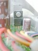
I have now have got out my glasses which focus at 10cm! The heat sunk device has D152 + possibly a further digit obscured with dirt. I can try and get a photo to show the shape of the 3 pin package - it has heavy leads going into the PCB. Obviously a power device. I would have guessed that the logic circuitry would not need much current, so I am inclined to think it is part of the motor power circuitry.

The 3 connections on the board have 24 KOhm to the battery negative, with one polarity of the multimeter, and over 20 MOhm with the other polarity, so I assume this indicates that the phase switching power FETs are not blown.

I have now recorded the connections for the lead going to the handlebar control as follows:
1. Pink-black
2. Black
3. Blue-black ... 0.7 Ohms to battery -ve connection
4. Lime
5. White
6. Violet
7. Brown
8. Pink
9. Green
10. Blue
11. Orange ... 3.28Kohm to battery +ve connection

When I connect the heavy power connectors to the battery (leaving the lead to the middle battery pin unconnected), the 2.5mF capacitor charges up to the battery voltage and discharges slowly over many minutes when the battery has been disconnected.

I have also checked the battery output again. With battery giving 25.2 V on the power pins, the middle pin sits at -19.2 V wrt the +ve pin (pin 1 in my notation) There are no volts measurable between the middle pin (pin 3 ) and the battery power -ve (pin4). I think that this implies that inside the battery pin 3 is connected through a diode to +6.0 V wrt pin 4, and -19.2 V wrt pin 1.

I had previously noticed that pin 3 remains exactly at 6 volts above pin 4 irrespective of the overall state of charge and therefore battery voltage. I think that this pin 3 voltage could be used to supply power to switch on the controller by means of the handle bar on/off push button.
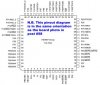
 

10mph

Esteemed Pedelecer
Dec 13, 2010
351
0
England
Hi Mike,

Perhaps you could provide details of the chips on the board? I'm curious to know if the microcontroller is just that (i.e. a programmed off the shelf chip) or if it is a custom asic...
I can't see any marking on the 64pin chip. or on the other ICs for that matter.

I agree it is likely to be some sort of ASIC or FPGA. It could well have an embedded controller. The chip on the pre-2006 model has the name Panasonic on it. Do Panasonic make generic processor chips? If not then it is likely that this was some Asic so might still be using something rather simlar - but there are many more pins now, so things would have been changed a lot.
 

z0mb13e

Esteemed Pedelecer
Jul 28, 2009
578
3
Dorset
I can't see any marking on the 64pin chip. or on the other ICs for that matter.

I agree it is likely to be some sort of ASIC or FPGA. It could well have an embedded controller. The chip on the pre-2006 model has the name Panasonic on it. Do Panasonic make generic processor chips? If not then it is likely that this was some Asic so might still be using something rather simlar - but there are many more pins now, so things would have been changed a lot.
If there are no markings then it is likely an off the shelf microcontroller as removing the markings was/is a common practice to disguise the chip and prevent tampering, reverse engineering or downloading the firmware. If you don't know what the chip is, it makes it that much harder to figure out where to start, security through obscurity.

Panasonic do make microcontrollers, but I don't know much about them.
 

z0mb13e

Esteemed Pedelecer
Jul 28, 2009
578
3
Dorset
I just had another thought, sometimes the PCBs get coated in flux when going through reflow ovens and this often coats the chips. Chips with very shallow etched marking can appear to have no markings. Cleaning the chips with IPA or similar solvent might reveal some markings.

EDIT: I've just had a look back at the photo and it looks like the whole board is immersed in potting compound. Is that the case? This could have the same effect as covering the chips with flux...
 
Last edited:

10mph

Esteemed Pedelecer
Dec 13, 2010
351
0
England
EDIT: I've just had a look back at the photo and it looks like the whole board is immersed in potting compound. Is that the case? This could have the same effect as covering the chips with flux...
Yes, it is potted with a film all over the top of the board, and probably underneath. Looks rather like the colour I remember of the polyurethane potting, Solithane, which I worked with 35 years ago. I may be able to peel it off the processor chip.
 

10mph

Esteemed Pedelecer
Dec 13, 2010
351
0
England
I have been photographing and after scrapping off the potting I can see in the enhanced photo faint etching as you suggested z0mb13e. It is invisible viewed directly with my eyes.

I dont think I have any IPA, but I will try and clean it up and get a photo.

For NRG here is a close up of the power transistor, again I have photoshopped it to try and maximise the contrast - I now think it only says D182 - but googling does not tell me what that is.
 

Attachments

z0mb13e

Esteemed Pedelecer
Jul 28, 2009
578
3
Dorset
I have been photographing and after scrapping off the potting I can see in the enhanced photo faint etching as you suggested z0mb13e. It is invisible viewed directly with my eyes.

I dont think I have any IPA, but I will try and clean it up and get a photo.

For NRG here is a close up of the power transistor, again I have photoshopped it to try and maximise the contrast - I now think it only says D182 - but googling does not tell me what that is.
With chips with etched markings, it is often easier to read them whilst holding it at an angle to a light bulb.

I can't make out what the 3 pin device is either - it could also say 82182 or 821B2, neither of which brings back any devices in google. The TR1 marking on the PCB suggests it is a transistor, but that isn't always reliable or accurate. Can you see a logo underneath the text?
 

10mph

Esteemed Pedelecer
Dec 13, 2010
351
0
England
Isn't this forum a wonderful place!

It has such helpful and knowledgeable people! Thanks to Z0mb13e I now know the controller is H8/3687 processor.

Here is some description which I googled:
The Renesas H8/3687 Processor
The H8/3687 Series is based on the H8/3664 Series and is designed for higher operating speed with an operating frequency of 20 MHz an a enhanced set of peripherals. These include extended timer channels, two serial interfaces, Power On Reset, Low Voltage Detect and a 14 bit PWM controller. While mostly upward compatible with the H8/3664, the differences particularly wit the timers, will mean that care must be taken when porting applications between the two processors.
Features:
Flash 56k In system programmable through the serial port with a built-in bootloader RAM 4k on chip Clocks 20MHz system clock
32kHz real-time sub-clock 8 bit timers RTC - extended version of the timer A 8 bit timer found in the H8/3664. Single channel, 8 bit, can be used as an interval timer or a clock time-base
Timer B1 - single channel, 8 bit timer
Timer V - single channel, 8 bit timer. Free running or external event counter with compare match 16 bit timers Timer Z - 2 channel, 16 bit. Each channel has 4 output compare/input capture registers. Watchdog timer Single channel, can be used as an interval timer Interrupts Internal - 38 sources
External - 11 sources A/D converter 8 channel, 10 bit, successive approximation I/O 45 general I/O
8 input only Serial devices IIC Bus interface
SCI3 - two serial channels that can be used as asynchronous or synchronous serial ports Others Power On Reset (optional)
Low Voltage Detect (optional)
14 bit PWM using pulse division Packages FP64A - QFP-64 (14mm x 14mm)
FP64E - LQFP-64 (10mm x 10mm)
 

10mph

Esteemed Pedelecer
Dec 13, 2010
351
0
England
Controller marking

I did not have any IPA so cleaned the chip with a Dettol kitchen cleaner and plenty of cotton buds.

See:
 

Attachments

kitchenman

Esteemed Pedelecer
Jul 9, 2010
1,309
7
Aberaeron, West Wales
It has such helpful and knowledgeable people! Thanks to Z0mb13e ...
I'm sharing in your enthusiasm and determination and only wish that I could help ...
 

z0mb13e

Esteemed Pedelecer
Jul 28, 2009
578
3
Dorset
It has such helpful and knowledgeable people! Thanks to Z0mb13e I now know the controller is H8/3687 processor.

Here is some description which I googled:
The Renesas H8/3687 Processor
The H8/3687 Series is based on the H8/3664 Series and is designed for higher operating speed with an operating frequency of 20 MHz an a enhanced set of peripherals. These include extended timer channels, two serial interfaces, Power On Reset, Low Voltage Detect and a 14 bit PWM controller. While mostly upward compatible with the H8/3664, the differences particularly wit the timers, will mean that care must be taken when porting applications between the two processors.
Features:
Flash 56k In system programmable through the serial port with a built-in bootloader RAM 4k on chip Clocks 20MHz system clock
32kHz real-time sub-clock 8 bit timers RTC - extended version of the timer A 8 bit timer found in the H8/3664. Single channel, 8 bit, can be used as an interval timer or a clock time-base
Timer B1 - single channel, 8 bit timer
Timer V - single channel, 8 bit timer. Free running or external event counter with compare match 16 bit timers Timer Z - 2 channel, 16 bit. Each channel has 4 output compare/input capture registers. Watchdog timer Single channel, can be used as an interval timer Interrupts Internal - 38 sources
External - 11 sources A/D converter 8 channel, 10 bit, successive approximation I/O 45 general I/O
8 input only Serial devices IIC Bus interface
SCI3 - two serial channels that can be used as asynchronous or synchronous serial ports Others Power On Reset (optional)
Low Voltage Detect (optional)
14 bit PWM using pulse division Packages FP64A - QFP-64 (14mm x 14mm)
FP64E - LQFP-64 (10mm x 10mm)
Now you know what chip it is, get the data sheet and start tracing the pins to see what does what! You will also be able to work out if the microcontroller is alive on your scope (check the supply voltage pins and the clock).

Or if you are feeling like a real hardcore reverse engineer, you could always invest in a JTAG rig and try and extract the firmware and work from that angle... (if the chip supports JTAG) :) (Something like the bus blaster or the wonderfully named Bus Pirate)
 

NRG

Esteemed Pedelecer
Oct 6, 2009
2,592
10
Wow, well done guys, looking forward to see how this progresses....
 

10mph

Esteemed Pedelecer
Dec 13, 2010
351
0
England
If I have got my device number codes correct here is the 500+ page data sheet for the controller, and this is the pinout:


I really think that is more than I want to know about the processor. Now what I need to do is find out how to power up the board.
 

Attachments

flecc

Member
Oct 25, 2006
53,575
30,859
10mph, since this unit was from John's failed Agattu, hasn't he got the handlebar unit that he can let you have? That could give you clues as to the power up wires and will also show which of the two multi-wire connectors it uses. There are two of those of course, the remaining two wire one presumably being for the optional pulse simulated 6 volt lighting current.
 

10mph

Esteemed Pedelecer
Dec 13, 2010
351
0
England
How the Panasonic Engineers developed their controller.

Flecc: John has got the bike working with a replacement Panasonic motor from another bike, so the handlebar unit is in use. I don't have the cheek to ask him to pull a working bike apart!

However, googling away I have just found a rather interesting article published in 2008, by RENESAS the manufacturer of the microcomputer, where they devote 3 pages to describing the work of Panasonic Cycle Technology and their use of The Renesas H8 in the controller see this pdf pages 12,13 and 20. complete with pictures of the managers and an engineer.

Photo 5 looks to be exactly the same version as Emmanuel's 2008 board which I linked here earlier today.

There is some nice very high level description, especially how they try out the bikes for over 500km in one month and the flash the memory to "adjust the personality of the product." I do like the personality of my Agattu which of course depends on both Panasonic and Kalkhoff. I wonder whether Kalkhoff also flash the memory.

z0mb13e was speaking earlier about reverse engineering the controller. That sounds a big project, I would rather just have instructions from Panasonic on how to modify and add my own code.
 

flecc

Member
Oct 25, 2006
53,575
30,859
Thanks for that 10mph. The old unit did have the facility for approved dealers to tweak the power very slightly, but I've seen no mention of that facility on the new units. Emmanuel did in fact open up two brand new 2008 units from different make bikes and found differences on the circuit boards, suggesting that bike manufacturer's requirements are met with specification variations.

Unfortunately at that point back in 2009 Emmanuel suffered a serious heart attack and has been unable to continue with this research.
 

z0mb13e

Esteemed Pedelecer
Jul 28, 2009
578
3
Dorset
Flecc: John has got the bike working with a replacement Panasonic motor from another bike, so the handlebar unit is in use. I don't have the cheek to ask him to pull a working bike apart!

However, googling away I have just found a rather interesting article published in 2008, by RENESAS the manufacturer of the microcomputer, where they devote 3 pages to describing the work of Panasonic Cycle Technology and their use of The Renesas H8 in the controller see this pdf pages 12,13 and 20. complete with pictures of the managers and an engineer.

Photo 5 looks to be exactly the same version as Emmanuel's 2008 board which I linked here earlier today.

There is some nice very high level description, especially how they try out the bikes for over 500km in one month and the flash the memory to "adjust the personality of the product." I do like the personality of my Agattu which of course depends on both Panasonic and Kalkhoff. I wonder whether Kalkhoff also flash the memory.

z0mb13e was speaking earlier about reverse engineering the controller. That sounds a big project, I would rather just have instructions from Panasonic on how to modify and add my own code.
Very interesting... especially the single wire debug feature. I was half joking about reverse engineering the controller. It is possible, but would take a lot of time and effort.

I would try and get the PCB out of the potting compound completely as it will make life easier and as was mentioned earlier there may be FETs on the underside of the PCB.
 

10mph

Esteemed Pedelecer
Dec 13, 2010
351
0
England
Board powered up

This morning I took the plunge, and on the 11 pin connector (to the handlebar unit) I shorted the orange lead (pin 11 in my notation) to pin3 - blue/black.

45 mA flowed through my short from pin 11 to pin 3, and it was encouraging to see that a greater current, 75 mA, flowed from the battery 25V terminal into the the board.

When I removed the short the battery current dropped to zero, so if the connection which I made emulates the function of the push button on/off switch on the handlebar unit, then that switch must be of a latching type ie push for on, then push again for off. If I had a handlebar unit which I could pull apart, it would be easy to verify that this is the case.

75mA does not seem to be to be very much for a microprocessor to be taking from the power supply, but then I am used to watt hungry PCs, and this is undoubtedly a comparatively low frequency - low power control system. I have not yet found out what current to expect the processor to draw.

With the unit "on" I then considered where I could probe voltages in order to find out what was happening. I was immediately faced with the problem of all the circuitry being under the potting. In time I will doubtless attempt the removal of the board and its potting, but there is the potential for damage during that process and I would like to get as far as I can without that.

I then realised that I had some the connector pins available where I could measure voltages:
So in pin order working from the top right towards the left of my labeled photo in an earlier post -
Torque sensor socket:
5.01 V
6.23 V
6.23 V
Hall Sensor Socket
3.63 V
0 V
5.01 V
5.01 V
5.01 V
5.01 V
I also measured the pin voltages on the two unconnected sockets
4 pin socket (3 pins used)
5.01 V red/black lead
24 mV yellow/black lead
0 V white/black lead
3 pin socket (with heavier contacts - so current carrying?)
0 V Black
5.01 V yellow
148 mV red

It is encouraging to see some sensible looking voltages on all these connectors. I am especially interested to see 5.01 volts appearing in many places because this could obviously be a 5volt circuit power bus. However, I think the processor itself works at 3V from what I have read.

I am reluctant to remove the potting so I can probe directly onto the processor pins. With 16 pins on a side of length 10 mm there is little margin to cope with the trembles of my hand, even if I could get some powerful magnification to see precisely what I was probing.

I think the next stage will be to remove the potting from the region immediately to the right of the Hall sensor connector. This is where I think the manufacturer may connect a test connector, and these pins are spaced wide enough that I will be able to probe without trouble. Also I think this will be the time to fire up the oscilloscope which I purchased for this task and see if I can see some clock waveforms.
 

z0mb13e

Esteemed Pedelecer
Jul 28, 2009
578
3
Dorset
This morning I took the plunge, and on the 11 pin connector (to the handlebar unit) I shorted the orange lead (pin 11 in my notation) to pin3 - blue/black.

45 mA flowed through my short from pin 11 to pin 3, and it was encouraging to see that a greater current, 75 mA, flowed from the battery 25V terminal into the the board.

When I removed the short the battery current dropped to zero, so if the connection which I made emulates the function of the push button on/off switch on the handlebar unit, then that switch must be of a latching type ie push for on, then push again for off. If I had a handlebar unit which I could pull apart, it would be easy to verify that this is the case.

75mA does not seem to be to be very much for a microprocessor to be taking from the power supply, but then I am used to watt hungry PCs, and this is undoubtedly a comparatively low frequency - low power control system. I have not yet found out what current to expect the processor to draw.

With the unit "on" I then considered where I could probe voltages in order to find out what was happening. I was immediately faced with the problem of all the circuitry being under the potting. In time I will doubtless attempt the removal of the board and its potting, but there is the potential for damage during that process and I would like to get as far as I can without that.

I then realised that I had some the connector pins available where I could measure voltages:
So in pin order working from the top right towards the left of my labeled photo in an earlier post -
Torque sensor socket:
5.01 V
6.23 V
6.23 V
Hall Sensor Socket
3.63 V
0 V
5.01 V
5.01 V
5.01 V
5.01 V
I also measured the pin voltages on the two unconnected sockets
4 pin socket (3 pins used)
5.01 V red/black lead
24 mV yellow/black lead
0 V white/black lead
3 pin socket (with heavier contacts - so current carrying?)
0 V Black
5.01 V yellow
148 mV red

It is encouraging to see some sensible looking voltages on all these connectors. I am especially interested to see 5.01 volts appearing in many places because this could obviously be a 5volt circuit power bus. However, I think the processor itself works at 3V from what I have read.

I am reluctant to remove the potting so I can probe directly onto the processor pins. With 16 pins on a side of length 10 mm there is little margin to cope with the trembles of my hand, even if I could get some powerful magnification to see precisely what I was probing.

I think the next stage will be to remove the potting from the region immediately to the right of the Hall sensor connector. This is where I think the manufacturer may connect a test connector, and these pins are spaced wide enough that I will be able to probe without trouble. Also I think this will be the time to fire up the oscilloscope which I purchased for this task and see if I can see some clock waveforms.
Sounds promising, 75mA is reasonable for a microcontroller not doing very much. I think I recall the mention of 11mA (or was that mW?) per MIPS in the last doc you linked to.

I don't know a lot about the panasonic drive system. How are the hall sensors arranged and how does the torque senser work?
 
Last edited:

flecc

Member
Oct 25, 2006
53,575
30,859
The power button is push for On, push again for Off, so probably latching:


Bear in mind that when switched on there is a 2 second self test, and if any torque sensing occurs during that period the unit will not function correctly and is usually very low on power if that happens.

The torque sensor has a centre tapped coil carrying balanced voltages, this surrounding an amorphous alloy sleeve with roughened bands which transmits the pedal force. The coils measure magnetic disturbances due to the distortion forces in the amorphous sleeve. I've got no measures of these since dynamic testing is so difficult to achieve. Amorphous sleeve in the upper pic, opened up coil unit below:


Last edited: