electric moped fault

billyboya

Esteemed Pedelecer
Aug 10, 2016
1,031
88
72
uk
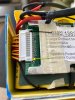
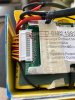
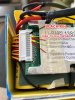
Pull out the White jst connector ( with the Yellow/Red and single Black wire).
You will need two needles/pins or some pcb strip pins.
Place one needle in the Black wire pin location and the other in the Yellow next to it, set your meter to 20v and write down the voltage as #1. (Black probe on Black and Red probe on Yel).
For #2 simply move the needle from Black pin to the first Red one and take a reading. (Black probe on Yel and Red probe on Red)
For #3 the needle in Yel moves to the next Yel for a reading ( the Balck probe always on the first needle as yuo move along and the Red probe always on the second needle).
For #4 the needle in the Red moves to the next Red and one takes a readiing, alternate the pin each time along the line until you have done so thirteen time to get thirteen individual voltage readings.
Once done post the results for us to see.

If you don't like the fact the needles are close together, take the readings as accumaltive ones and write them down (set the meter to 200v).
Once you have done the first cell reading as above, leave the needle in the Black pin out location all the time and only move the second needle along one pin at a time.
You will see readings like 3.8, 7.6, 11.4, 15.2 etc, etc until you have thirteen with the last being approx. 49.7.

Once we can see the results we can see if their is a balance issue or whether the non charging may simply be a bms issue.

Hi Nealh Ok I am with you so far but where do I get these >>>>> You will need two needles/pins or some pcb strip pins.


are you on about sowing needle and pins. so the pins I check is what that JST plug was plugged into.
I can remember doing this on that old battery I had on moped. but pins are so close and I am afraid I may touch 2, But I think I can be very careful as no hurry. Yes can remember writing down readings on old battery

PINS.JPG
 
Last edited:

Nealh

Esteemed Pedelecer
Aug 7, 2014
20,236
8,250
60
West Sx RH
Sewing needles or dressmakers pins are fine, the pinstrip is a PCB strip or arduino strip. The pins are seprated by the plastic strip they are in, the former are likely easier to have at hand.

If concerned about probes accidently toucing then in between the needles slip a thin piece of pastic or card for insulation in case of a slip or use a thin lolly stick.

Any accidental touching causing a spark is momentary and won't initially cause and harm, though the probe ends may melt a bit or pit. The harm is done with prolonged sparking/arcing.
 
Last edited:

billyboya

Esteemed Pedelecer
Aug 10, 2016
1,031
88
72
uk
Sewing needles or dressmakers pins are fine, the pinstrip is a PCB strip or arduino strip. The pins are seprated by the plastic strip they are in, the former are likely easier to have at hand.

If one accidently touches the probes whilst on the pins then the spark is very momentary and will cause no damage, after the first touch one learns to be very careful.
A prolonged touch with pit burn the probe ends or the needles it shouldn't cause any cell harm initiallEdity as a one off.

Oh I am with you now as a needle with be much thinner than meter probs. Just need to remember which pins I have checked so may just very carefully write in black pen on connecter pins or white plug

is this right as I just counted 12 pins including that 1st black one. so actually Im only checking 11 pins is that right
 

Nealh

Esteemed Pedelecer
Aug 7, 2014
20,236
8,250
60
West Sx RH
You are counting the pins on the bms side , these aren't used for measuring.
You place the needles in the pin out holes on the plug end which is wired, it is these wires that are soldered to the cells.

There are 13 coloured wires and 1 Black, the battery is 13s so there has to be 13 readings.
If doing individual cell readings the Black is the Gnd for the first cell group then as one moves the 2nd pin along each time the previous pin acts as the gnd for measuring as only single cell readings are taken.

If one uses the gnd Black pin all the time, one only has to move one pin each time to the next pin out for acumaltive readings.
It is easier though to simply to have single cell readings.
 
Last edited:

billyboya

Esteemed Pedelecer
Aug 10, 2016
1,031
88
72
uk
You can't count :eek:.
There are 13 coloured wires and 1 Black, the battery is 13s so there has to be 13 readings.
I need stronger glasses lol. as black pin is under that lug same at other end another yellow so 14 including black lol. Now I have just carefully placed black probe on black pin. red probe on pin next to it. meter at 20V DC and no reading at all. Not tried other pins yet.

PINS2.JPG
 

Nealh

Esteemed Pedelecer
Aug 7, 2014
20,236
8,250
60
West Sx RH
I need stronger glasses lol. as black pin is under that lug same at other end another yellow so 14 including black lol. Now I have just carefully placed black probe on black pin. red probe on pin next to it. meter at 20V DC and no reading at all. Not tried other pins yet.

View attachment 47480
Read the first lines of #184 you won't get any readings from the bms side, pull out the wired connector fully and insert the needles in the female pins outs.
 

billyboya

Esteemed Pedelecer
Aug 10, 2016
1,031
88
72
uk
Im getting a bit confused here as you put

For #2 simply move the needle from Black pin to the first Red one and take a reading. (Black probe on Yel and Red probe on Red)

its like black pin to 1st red, but in brackets you say black probe on yel red on red
 

billyboya

Esteemed Pedelecer
Aug 10, 2016
1,031
88
72
uk
Read the first lines of #184 you won't get any readings from the bms side, pull out the wired connector fully and insert the needles in the female pins outs.
Oh bloody hell no wonder now I can see where Im going wrong. ok can now see the idea of a needle ok sorry will try again. But still a bit confused in the order I can do 1st lot ok black to black wire then red to 1st yellow next to it,

But its after that


Ive just done #1 ok it says 4.26v but now i m confused how to do others
 
Last edited:

billyboya

Esteemed Pedelecer
Aug 10, 2016
1,031
88
72
uk
Im so sorry about all this But the 1st part was easy black probe in black red in next hole yellow

But thats now where I cant understand #2 it says move black pin to 1st red one and take a reading but where does red probe go as in brackets you have put (Black probe on Yel and Red probe on Red)

so I dont touch needle in black pin no more just keep black prob on yel wires and red on red all way along

like black/yel

red/red pins

I will have to come back when you reply again as I am a bit confused now

and don't want to mess up
 
Last edited:

Nealh

Esteemed Pedelecer
Aug 7, 2014
20,236
8,250
60
West Sx RH
Oh bloody hell no wonder now I can see where Im going wrong. ok can now see the idea of a needle ok sorry will try again. But still a bit confused in the order I can do 1st lot ok black to black wire then red to 1st yellow next to it,

But its after that
For individual cell reading only move the first pin to the next unoccupied pin hole.
So once you have reading for cell #1 Black pin and first Yellow, move the needle from Black pin to next pin (Red) the other side of Yellow, this is reading #2. Yellow then becomes the Gnd for for the Black probe and the Red probe goes to the Red wire.

Once #2 cell is done, the needle you move always moves to the same wire colour it has come from as it alternates colour.
For #3 move the needle to the other side of the Red wire in to the next Yellow, this Yellow is where the Red probe goes and the Black probe goes on the previous Yellow wire.

Move along each pin one at time like this until you have 13 voltage readings, always move only one pin to the next unoccupied pin hole. Every time you move the needle along the connector to the next available hole this pin always becomes the Red probe for measuring a + reading. If you reverse the probes you will see the same voltage reading but with a - in front which indicates a reverse polarity reading. Nothing will happen, it's just an erronous probe reading for polarity.

As I mentioned if worried about sparking/accidental probes touching'slipping, place a bit of thin card froma cereal packet between the needles so needles and probes can't cross touch each other.
 
Last edited:

billyboya

Esteemed Pedelecer
Aug 10, 2016
1,031
88
72
uk
For individual cell reading only move the first pin to the next unoccupied pin hole.
So once you have reading for cell #1 Black pin and first Yellow, move the needle from Black pin to next pin (Red) the other side of Yellow, this is reading #2. Yellow then becomes the Gnd for for the Black probe and the Red probe goes to the Red wire.
For #3 move the needle to the other side of the Red wire in to the next Yellow, this Yellow is where the Red probe goes and the Black probe goes on the previous Yellow wire.

Move along each pin one at time like this until you have 13 voltage readings, always move only one pin to the next unoccupied pin hole. Every time you move the needle up the connector to the next available hole this pin always becomes the Red probe for measuring a + reading. If you reverse the probes you will see the same voltage reading but with a - in front which indicates a reverse polarity reading. Nothing will happen, it's just an erronous probe reading for polarity.

As I mentioned if worried about sparking/accidental probes touching'slipping, place a bit of thin card froma cereal packet between the needles so needles and probes can't cross touch each other.


Sorry about all this Nealh so am I correct then in saying after I have checked black prob in black pin red in 1st yellow next to black pin thats #1

so on #2 its black pin on red 3rd pin along and red on yellow 4th pin along

#3 black prob on 5th pin RED red on 6th pin yellow

#4 blck prob 7th pin red red on 8th pin yel


so like black on yel red on red just keep moving along to end like alternating and Im not touching those pins just the connecter holes

1.JPG
 
Last edited:

billyboya

Esteemed Pedelecer
Aug 10, 2016
1,031
88
72
uk
I will take a break from all this as I just get so confused Im sorry will come back later its just a pity I know what colour wires I touch black prob on and what colour red prob it seems to be black on red and red on yellow all way along plug to end

dont suppose by my image you can mark wires colours to what colour probe
 

Nealh

Esteemed Pedelecer
Aug 7, 2014
20,236
8,250
60
West Sx RH
Ok start again, in all there are 14 pins call Black wire no 1 pin which initially is B0 or 0v (it carries no voltage) , the next Yellow no 2 pin is cell group #1 and the next Red no 3 pin is cell group # 2 and so on until you get to the 14th pin which is cell group #13. The 13 Yellow/Red wires are the 13 cell groups.
#1 cell group is pin 2 yellow wire so Red probe on pin 2 & Blk probe on pin 1.
#2 cell group is pin 3 Red wire so Red probe on pin 3 & Blk probe on Yellow wire before it.
#3 cell group is pin 4 Yellow wire so Red probe on pin 4 & Blk probe on Red wire before it.
#4 cell group is pin 5 Red wire so Red probe on pin 5 & Blk probe on Yellow wire before it.
#5 cell group is pin 6 Yellow wire so Red probe on pin 6 & Blk probe on Red wire before it.
#6 cell group is pin 7 Red wire so Red probe on pin 7 & Blk probe on Yellow before it and so on and so on until you get to the very end where #13 cell group is pin 14 Yellow so Red probe on pin 14 and Blk probe on the Red pin before it .
Alternating one should get 13 cell readings of 3.81v or 3.82v or similar if they are all balanced.
 

billyboya

Esteemed Pedelecer
Aug 10, 2016
1,031
88
72
uk
Ok start again, in all there are 14 pins call Black wire no 1 pin which initially is B0 or 0v (it carries no voltage) , the next Yellow no 2 pin is cell group #1 and the next Red no 3 pin is cell group # 2 and so on until you get to the 14th pin which is cell group #13. The 13 Yellow/Red wires are the 13 cell groups.
#1 cell group is pin 2 yellow wire so Red probe on pin 2 & Blk probe on pin 1.
#2 cell group is pin 3 Red wire so Red probe on pin 3 & Blk probe on Yellow wire before it.
#3 cell group is pin 4 Yellow wire so Red probe on pin 4 & Blk probe on Red wire before it.
#4 cell group is pin 5 Red wire so Red probe on pin 5 & Blk probe on Yellow wire before it.
#5 cell group is pin 6 Yellow wire so Red probe on pin 6 & Blk probe on Red wire before it.
#6 cell group is pin 7 Red wire so Red probe on pin 7 & Blk probe on Yellow before it and so on and so on until you get to the very end where #13 cell group is pin 14 Yellow so Red probe on pin 14 and Blk probe on the Red pin before it .
Alternating one should get 13 cell readings of 3.81v or 3.82v or similar if they are all balanced.

Ok Nealh I will study this better, But ATM I have a very bad headache so need to take a break, not to do with all this. But cant concentrate right now. I think I'm getting it now better. will let you know results later
 

Nealh

Esteemed Pedelecer
Aug 7, 2014
20,236
8,250
60
West Sx RH
I find it is best when in a better frame of mind to get ones head around it if one can't take it in or understand, this is what I did when Guerney was helping me with the setting up of the JAVA download programme for this retched pc/laptop.
Batteries and buidling etc,etc I find easy but programming and pc faffing is all gobbledygook stuff at times to me.
 

Nealh

Esteemed Pedelecer
Aug 7, 2014
20,236
8,250
60
West Sx RH
You will be on your own for this afternoon or early eve as I'm off to work soon.
 

billyboya

Esteemed Pedelecer
Aug 10, 2016
1,031
88
72
uk
I find it is best when in a better frame of mind to get ones head around it if one can't take it in or understand, this is what I did when Guerney was helping me with the setting up of the JAVA download programme for this retched pc/laptop.
Batteries and buidling etc,etc I find easy but programming and pc faffing is all gobbledygook stuff at times to me.

Well I am opposite I am into PC building, about to build myself a better one. mine is from Noah's Ark now LOL.

or from dinosaur age. Just got new Mother board, GFX card, CPU, PSU. and Ram cost a fortune. But if i want better PC well best to spend a bit
 

billyboya

Esteemed Pedelecer
Aug 10, 2016
1,031
88
72
uk
You will be on your own for this afternoon or early eve as I'm off to work soon.

its ok its fine IM no hurry to fix battery or Moped. cant sell if its not running, as doubt also will get about £50 to £100 for spares or repair. at least if its all running, will get a bit more not much though.
 

Nealh

Esteemed Pedelecer
Aug 7, 2014
20,236
8,250
60
West Sx RH
You need to think of the battery in the same way you think about pc's then.
If you want a better battery well best to spend a bit.
 

soundwave

Esteemed Pedelecer
May 23, 2015
16,393
6,353