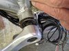
The central rotating part with plastic grippy teeth grab hold on the taper square axle for a firm fixing, the outer part remains in a fixed position and as you can see it has splines that are meant to locate into the BB shell face. At least 8mm gap is needed.
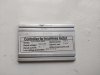
I have just noticed you don't have the V12L but the V6 dual hall model, only difference is it works off 6 pulses and not 12. C1 05 -07 should still be the setting to try.
I have just noticed you don't have the V12L but the V6 dual hall model, only difference is it works off 6 pulses and not 12. C1 05 -07 should still be the setting to try.
Last edited: