Hall sensor configuration possibly causing C3 error?

crystaljohn

Pedelecer
May 29, 2019
138
27
36988I have been wrestling with the reason for a C3 on my LCD display and not being able to get my Powabike Cambridge ebike working.

I bought a second hand Powabike Cambridge model ebike last year as my first ebike and this was my first introduction to the wonderful world of e bikes.

It went well for about 4 months until it suddendly stopped working. I bought a new controller and LCD display as I jumped to the conclusion that the controller was not working.
24V/36V 250W 6Mosfets 15A Brushless DC Sine Wave Controller36987

After installing the new controller and LCD all appeared normal on the LCD display, but as soon as the throttle was activated I kept getting a C3 error ( Hall sensor abnormality) showing and I couldn't get the bike to work. I spent a long long time checking everything was correctly installed, good continuity accross the connections etc.

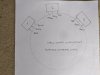
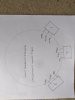
To cut a very long story short* I eventually stripped the hub motor apart and replaced the 3 Hall sensors. ( I did notice that the middle Hall senor was in a different configuration from the outer 2 Hall sensors, in that it was reversed relative to the outer 2 sensors. see my diagram:


After careful installation of the new sensors ;and testing the sensors with a newly arrived from China ebike multi function tester which seemed to show the Hall sensors working correctly, I switched on and as soon as the throttle is activated I again get the C3 error message ( Hall sensor abnormality).

So, I am wondering is the controller is not compatible with the way the Hall sensors and associated wiring is configured in the original Powabike set up, and it's the way the Hall sensors are configured that is causing the conflict I am experiencing?


*https://www.pedelecs.co.uk/forum/threads/advice-appreciated-new-controller-purchase.36050/page-2
 
Last edited:

vfr400

Esteemed Pedelecer
Jun 12, 2011
9,822
3,986
Basildon
Which controller did you get? The ideal one would have had fully automatic phase angle and hall configuration, but I think the ones with the self-learning wires might be a able to figure it out as well - maybe not the phase angle
 
  • Like
Reactions: crystaljohn

crystaljohn

Pedelecer
May 29, 2019
138
27
I got this one:http://www.pswpower.com/ven.php?cargo.2016-3f-3f7c

( I think it was you that recommended it)

I have been struggling with this problem for ages, checked everything over hundreds of times, refusing to give up as I really enjoyed riding this bike. I am very sure all the connections are sound and everything is wired up correctly.
It was only when I replaced the Hall senors that I became aware of how they are configured so was extremely careful replacing them in exactly the same way.

I even bought an ebike tester ,and although the instructions were difficult to understand , the tester indicated that they were doing what the instructions said shoud happen.

I have only just thought about how the Hall sensors are orientated being a possible cause of the C3 error.
 

crystaljohn

Pedelecer
May 29, 2019
138
27
I have also wondered if my problem might be resolved if I orientate the middle Hall sensor to match the other 2 outer sensors?
 

vfr400

Esteemed Pedelecer
Jun 12, 2011
9,822
3,986
Basildon
I'm not sure about this, but I've got a feeling that the hall orientation relates to the phase angle. Unfortunately, the KT controller, though very versatile, has to be manually configured to match the motor characteristics.
 
  • Like
Reactions: crystaljohn

crystaljohn

Pedelecer
May 29, 2019
138
27
Ok, I understand.
Is it possible that you might be able to guide me through the process?
I am familiar with changing the parameters using the KT panel.
 

vfr400

Esteemed Pedelecer
Jun 12, 2011
9,822
3,986
Basildon
Neal's quite good at this, and I'll help if I can. The first step is to list up all your P and C parameters from the settings (L if you have any), then we can see, which ones have a chance of being changed for the better. We're in the realms of the unknown, but maybe some learning can come from this if nothing else.
 
  • Like
Reactions: crystaljohn

crystaljohn

Pedelecer
May 29, 2019
138
27
Neal's quite good at this, and I'll help if I can. The first step is to list up all your P and C parameters from the settings (L if you have any), then we can see, which ones have a chance of being changed for the better. We're in the realms of the unknown, but maybe some learning can come from this if nothing else.
Ok
I will hopefully be able to list up my stored parameters this weekend.
I have the bike stored away from my house ATM
 

crystaljohn

Pedelecer
May 29, 2019
138
27
Just remembered I have the parameters I have inputted written down.

P1---120 (I put this value as I worked out the reduction gears were in the ratio of 6:1 and I have 20 magnets. so 6 x20 = 120)

P2---5 ( motor pulse magnet setting)

P3---1 ( change relationship of pas to throttle)

P4---0 ( throttle can work at any time)

P5---15 ( battery voltage level)

C1---5 ( Pas settings )

C2---0 ( Motor Phase Classification Coding Mode)

C3---8 ( level of pedal assist)

C4---0 ( throttle works full power)

C5---10 (max controller output)

C6---3 ( back light brightness)

C7---0 ( crusie function : zero =off 1 = on

C8---0 ( motor temperature- only works if sensor installed)

C9---0 (password) I don't use one

C10---N

C11---0 ( communication protocol setting) leave at zero

C12---4 ( minimum voltage cutoff - I have 36 v battery so have set to 4

C13---0 ( regen braking)

C14---2 ( pas tuning setting)


I used this helpful video to choose my settings:

 
Last edited:

Nealh

Esteemed Pedelecer
Aug 7, 2014
20,171
8,238
60
West Sx RH
You can try changing C2 to see if any of them change the phase/hall configuration.
Other wise you can try to manually swap the hall/phase sequence to see if any combo works (in all there are 36 possibles), we had the same problem on another thread where the phase angle was different and the chap had a devil of a time getting a sequence although eventually I think 2 or 3 turned up that worked.

Phase-Hall-Wire-Combinations.png
 
  • Like
Reactions: crystaljohn

crystaljohn

Pedelecer
May 29, 2019
138
27
Thanks Neil

I can manage experimenting with changing the C2 parameters, that's straightforward for me.

The chart looks complicated at first glance. I will need to study it more to hopefully understand it. I think I understand that it displays most of the possible combinations of how the 3 colours of the sensor wires can be connected relative to the 3 phase wires.
 

crystaljohn

Pedelecer
May 29, 2019
138
27
I think I have the gist of it now ( famous last words )

I would appreciate some more information.

What are the abreviations: B/V

C/W

A/U


And: CONT and MOT.
 

vfr400

Esteemed Pedelecer
Jun 12, 2011
9,822
3,986
Basildon
Nothing to worry about. The phases are normally labelled, U, V and W on ebikes, but sometimes A, B and C on other applications. CONT = controller side. MOT - motor side.

Three of the 36 combos will give you the correct forward motion, 3 will give backwards motion, so you shouldn't have to do all 36. There are often asymmetries between the phases, so one of the three correct combos might be better than the other two, but you need a wattmeter to measure the no-load current to find out which one.
 
Last edited:

Nealh

Esteemed Pedelecer
Aug 7, 2014
20,171
8,238
60
West Sx RH
Also for C1 we need to know the PAS type/desination in use as the wrong setting can render PAS operation useless.

On another thread a guy was at the point of frustration as he couldn't get any power from the motor via PAS, simply the C1 value was incorrect for the sensor in use. He changed it to the value I suggested and he was happy as Larry.
With any of the P or C changes one needs to understand how they affect the system.

For the C2 setting ideally you need PAS to be working as the wrong phase setting using throttle as power could damage the controller (you will know a bad setting from the awful growls), I always test in PAS level 1 or 2 so the current drawn is low once happy with the operation I use throttle to fully test.
 
  • Like
Reactions: crystaljohn

crystaljohn

Pedelecer
May 29, 2019
138
27
Thanks for the explanation.

I have just tried altering the C2 parameters. I was set on zero. I tried all values from 1-5 with the result -no change- I am still getting the C3 error.

I will now try the changes to the combinations of the wiring.

need to remove the male pins from the hall sensor 6 way plug. I see that there is a 'barb' locating the pin in the plug. I vaugly recall seeing a tool that one can use to extract the pin.

Can anyone point me in a direction where I might buy one of these tools, or suggest anyway of removing the pins please.
 

Nealh

Esteemed Pedelecer
Aug 7, 2014
20,171
8,238
60
West Sx RH
I think I have the gist of it now ( famous last words )

I would appreciate some more information.

What are the abreviations: B/V

C/W

A/U


And: CONT and MOT.
Using a seperate sheet of A4 right down each test result when applied ie; noise made, rotation, stuttering, smoothness of operation.
 
  • Like
Reactions: crystaljohn

crystaljohn

Pedelecer
May 29, 2019
138
27
Nealh I havn't tried rotating the crank to see if the P.A.S sensor will switch on power to the motor as I have had a limited focus on the fact that as soon as I twist the throttle I see the c3 error.
I am using the existing P.A.S that was on my bike when I bought it . It has 8 'poles' and I chose the c1 value of 5.
 

Nealh

Esteemed Pedelecer
Aug 7, 2014
20,171
8,238
60
West Sx RH
Thanks for the explanation.

I have just tried altering the C2 parameters. I was set on zero. I tried all values from 1-5 with the result -no change- I am still getting the C3 error.

I will now try the changes to the combinations of the wiring.

need to remove the male pins from the hall sensor 6 way plug. I see that there is a 'barb' locating the pin in the plug. I vaugly recall seeing a tool that one can use to extract the pin.

Can anyone point me in a direction where I might buy one of these tools, or suggest anyway of removing the pins please.
I have used a sewing needle or very thin flat blade micro screwdriver to tease the barb allowing it to then be pulled.

Changing C2 means nothing if you don't know the sensor used is it DL 12, V12L or a std single hall type as one will be guessing all the time if it is a correct setting.
 

vfr400

Esteemed Pedelecer
Jun 12, 2011
9,822
3,986
Basildon
Thanks for the explanation.

I have just tried altering the C2 parameters. I was set on zero. I tried all values from 1-5 with the result -no change- I am still getting the C3 error.

I will now try the changes to the combinations of the wiring.

need to remove the male pins from the hall sensor 6 way plug. I see that there is a 'barb' locating the pin in the plug. I vaugly recall seeing a tool that one can use to extract the pin.

Can anyone point me in a direction where I might buy one of these tools, or suggest anyway of removing the pins please.
I use a darning needle, a large paper clip, a piece of piano wire, a micro screwdriver set that I got in a Christmas cracker, other small screwdrivers and things like that.
 
  • Like
Reactions: crystaljohn

crystaljohn

Pedelecer
May 29, 2019
138
27
Is my understand correct, that there are 2 ways of activating power supplied to the motor.

1. by twisting the throttle.

2. by revolving the crank so that the controller recognises that a signal is being produced .