

pro rider electric bike help
- Thread starter garysnooker
- Start date
Hi the First test passed could you tell me what wires.i need to join pls i now have a Multimeter but dont know how to ues it lolIf the display doesn't switch on, it's a sign that you have failed test 1 above.
You can work the bike without the display if it's faulty, but you need to join some wires. First the bike needs to pass test 1.
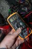
So you pulled the controller out and measured the voltage on the bullet connectors while connected, right? What voltage did you get?Hi the First test passed could you tell me what wires.i need to join pls i now have a Multimeter but dont know how to ues it lol
THANKS FOR YOUR ON THIS I THINK IT WAS 38 voltageSo you pulled the controller out and measured the voltage on the bullet connectors while connected, right? What voltage did you get?
Measure it again and give us the exact voltage.THANKS FOR YOUR ON THIS I THINK IT WAS 38 voltage
thank you so much for help will do that frist think tomow
thank you so much for help i will do that frist think tomorrow i all so brought this hoping it would help https://www.ebay.co.uk/itm/383711198820
thank you so much for help i will do that frist think tomorrow i all so brought this hoping it would help https://www.ebay.co.uk/itm/383711198820
Hi thanks for your help if it comes to it i thought i might buy this https://www.ebay.co.uk/itm/124332332244?ssPageName=STRK:MESINDXX:IT&_trksid=p3984.m1436.l2649 do you think it would work its a old bike
Attachments
-
 1.2 MB Views: 6
Rather than spend money, you need to find out what's wrong.
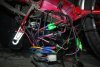
Step 2. Measure the voltage between the black battery wire and any of the thin red ones that go to the throttle, PAS or motor hall sensors. It should be around 5v. If you don't have 5v, take a photo of all the wires and connectors attached to the controller spread out so that we can see exactly what you have.
Step 2. Measure the voltage between the black battery wire and any of the thin red ones that go to the throttle, PAS or motor hall sensors. It should be around 5v. If you don't have 5v, take a photo of all the wires and connectors attached to the controller spread out so that we can see exactly what you have.
For measuring battery voltage use the 200v scale for a bit more accuracy.Hi thanks for your help if it comes to it i thought i might buy this https://www.ebay.co.uk/itm/124332332244?ssPageName=STRK:MESINDXX:IT&_trksid=p3984.m1436.l2649 do you think it would work its a old bike
For the 5v measurements use the 20v scale.
Last edited:
Hi ive Measure the voltage between the black battery wire and any of the thin red ones im not geting any reading at allRather than spend money, you need to find out what's wrong.
Step 2. Measure the voltage between the black battery wire and any of the thin red ones that go to the throttle, PAS or motor hall sensors. It should be around 5v. If you don't have 5v, take a photo of all the wires and connectors attached to the controller spread out so that we can see exactly what you have.
Attachments
-
 3.5 MB Views: 9
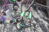
You have a flat 6-pin connector with red, pink, grey, blue and black wires in it. Put your blanck probe on the battery black and probe up the back of that connector on the controller side.
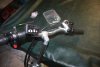
Do you have some sort of control panel on the handlebars? Please show a photo of the handlebars that shows everything on them, especially any switches or throttle.
Do you have some sort of control panel on the handlebars? Please show a photo of the handlebars that shows everything on them, especially any switches or throttle.
no reading at allYou have a flat 6-pin connector with red, pink, grey, blue and black wires in it. Put your blanck probe on the battery black and probe up the back of that connector on the controller side.
Do you have some sort of control panel on the handlebars? Please show a photo of the handlebars that shows everything on them, especially any switches or throttle.
Attachments
-
 3.7 MB Views: 12
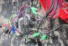
OK. As far as I can see the lighting wires have been bodged. I'm pretty sure that the wires for the lights are the reds and blacks on the left side of the photo. Unfortunately, your photo doesn't show where the wires at the bottom right come from or go to, and I assume that they're what's powering the lights now.Hi its for the lights
The red wire next to the pink in the 6-way connector is what powers the control panel and the pink powers the controller when the panel is switched on. That red wire is connected directly to the thick red battery wire inside the controller, so it's normally impossible to have 39v on the battery wire and nothing on that thin wire unless there's a separate ignition switch or loop.
Working from left side across and down, the wires are:
Lights
Brakes
Battery
Control panel
PAS
Throttle
Motor phase wires
Motor hall sensor wires
Can you take a photo with those all cleared out the way, so that I can see what's going on with the wires on the right - where and how they're attached to the controller?
That means that it doesn't have 0v on it. Measure it again.i accidentally touch the red wire on the flat 6-pin connector and it spark
i Measure the back wire on the 6-pin connector no reading
Attachments
-
 4.4 MB Views: 10
 -
 4.3 MB Views: 9
Related Articles
-
 MTF Enterprises announces acquisition of EMU Electric Bikes
- Started by: Pedelecs
-
 Wisper 806T folding bike wins Which? ‘Best Buy’
- Started by: Pedelecs
-
 Sustrans calls for protected cycle lanes
- Started by: Pedelecs
-
 Amazon launch their first UK e-cargo micromobility hub
- Started by: Pedelecs
