

Hi there, do you know where I can get a c500 lcd display unit, the 1 I have on my Ebike just went blank. Any help would be much appreciated. Thanks Stevie.C500 is a Bigstone brand compatible with Bafang controllers and might be so with Lishui.
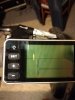
Hi there, do you know where I can get a c500 lcd display unit, the 1 I have on my Ebike just went blank. Any help would be much appreciated. Thanks Stevie.C500 is a Bigstone brand compatible with Bafang controllers and might be so with Lishui.
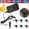
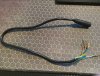
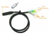
So I don't need the hub wheel connected to the controller and battery if I use 4-6v charger. Would this work https://www.ebay.co.uk/itm/402761003082 i could put the red and black cable into it? Thank you£10 for a motor cable from Ebay. Cut the connector off attach a 4 - 6v charger to the red and black wires, then you can test the halls on the other wires.
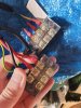
I really like this idea. Even i could do it because you don't need to solder. I have a block from my old kit however I dont think it has 9 separate slots. Ill go and find it. Thanks Nealh and nice to see youAs vfr has said the are ways to test with the motor cable , just a case of being a bit more inventive .
If you want to be really clever use a double end motor/controller cable , cut it in half and then join all the wires to a block connector so they are colour to colour. Connect the moulded connectors to the motor and controller ends, one can then stick the meters probes in to the block connector for testing.
When done remove the test cable and reconnect the fitted cables as normal.
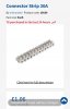
You will need a block connector or two smaller ones so that none of the wires short by touching each other.
£10 or so to make up the wire for testing will take away the guess work in buying parts that you might not need.
Does this video explain it? In sharing the link in case it could help others who are visual thinkersFor mosfets one simply probes the controller phases with no power source needed.
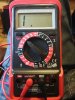
Use the 200k scale and try again.I tried this on two other controllers (500 and 1000w direct drives) and it works, the meter chargers the capacitors. If I reverse the polarity all three controller capacitors begin to drain yet this one won't charge or at lease doesn't show a voltage indication of increase.
No difference. I went upto 20m.Use the 200k scale and try again.


