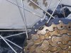
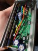
Hello. My controller has three metal pieces which are screwed in behide the mosfets to apply pressure to case. If I remove the side screws these will all drop out. Ill be able to put the side ones back in but not the middle as I won't be able to get my fingers in to push it against the case.You can leave the freewheel on if you can get at the side-plate screws.
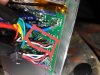
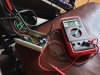
It's easier to test the halls in the controller as long as you're careful not to short anything with the probes. Use a helper to turn the wheel backwards while you measure.
I had a quick look at removing with the freewheel on however the low cog might be too large. Ill check later thank you.